Lead electrode for use in an MRI-safe implantable medical device

a safe, implantable technology, applied in the field of implantable medical devices, can solve the problems of unfavorable mri scanning, potential risk associated with undesirable interaction between the mri environment and the above-described neurostimulation system, and achieve the effect of reducing the risk of mri scanning and mri scanning

Active Publication Date: 2007-02-06
MEDTRONIC INC
View PDF151 Cites 375 Cited by
  • Summary
  • Abstract
  • Description
  • Claims
  • Application Information

AI Technical Summary

Problems solved by technology

In fact, the MRI is now considered by many to be the preferred standard of care, and failure to prescribe MRI scanning can be considered questionable.
Thus, questions have arisen regarding the potential risk associated with undesirable interaction between the MRI environment and the above-described neurostimulation systems; e.g. forces and torque on the implantable device within the MRI scanner caused by the static magnetic field, RF-induced heating, induced currents due to gradient magnetic fields, device damage, and image distortion.

Method used


Image

  • Lead electrode for use in an MRI-safe implantable medical device
  • Lead electrode for use in an MRI-safe implantable medical device
  • Lead electrode for use in an MRI-safe implantable medical device

Examples


Embodiment Construction

[0038]The following detailed description of the invention is merely exemplary in nature and is not intended to limit the invention or the application and uses of the invention. Furthermore, there is no intention to be bound by any theory presented in the preceding background of the invention or the following detailed description of the invention.

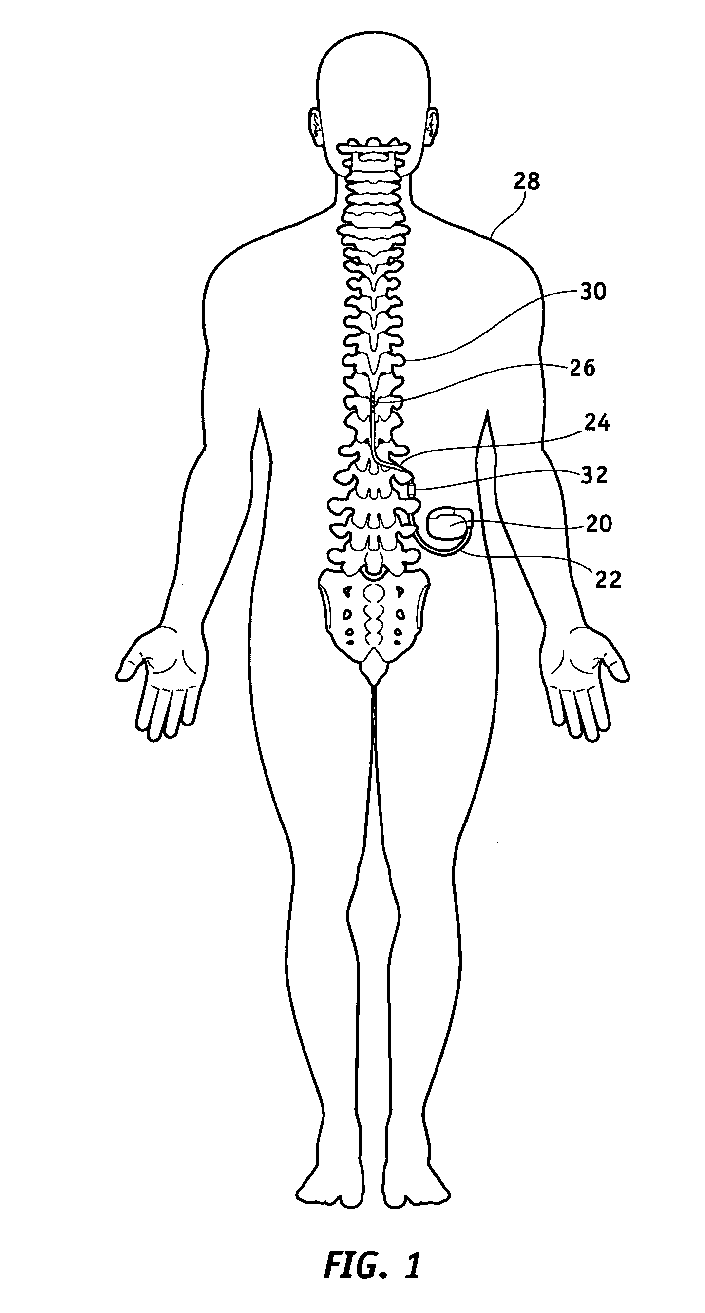
[0039]FIG. 1 illustrates a typical SCS system implanted in a patient. As can be seen, the system comprises a pulse generator such as an SCS neurostimulator 20, a lead extension 22 having a proximal end coupled to neurostimulator 20 as will be more fully described below, and a lead 24 having proximal end coupled to the distal end of extension 22 and having a distal end coupled to one or more electrodes 26. Neurostimulator 20 is typically placed in the abdomen of a patient 28, and lead 24 is placed somewhere along spinal cord 30. As stated previously, neurostimulator 20 may have one or two leads each having four to eight electrodes. Such a sys...


PUM


Abstract

A pulse stimulation system configured for implantation into a patient's body comprises a pulse stimulator, a conductive stimulation lead having a proximal end electrically coupled to the pulse simulator and having a distal end, and an electrode assembly coupled to the distal end of the stimulation lead. The electrode assembly comprises an electrode body having a therapy electrode thereon that is electrically coupled to the stimulation lead for delivering therapy to the patient. A floating electrode is configured to contact the patient's body tissue and has a surface area substantially larger than that of the therapy electrode. A filter is coupled between the therapy electrode and the floating electrode for diverting RF energy toward the floating electrode and away from the therapy electrode.

Description

CROSS-REFERENCES TO RELATED APPLICATIONS[0001]This application claims the benefit of U.S. Provisional Application No. 60 / 557,991, filed Mar. 30, 2004.FIELD OF THE INVENTION[0002]The present invention generally relates to implantable medical devices, and more particularly to a lead electrode for use in conjunction with an implantable medical device such as a neurostimulation system which, when used in an MRI (Magnetic Resonance Imaging) environment, dissipates or directs energy at MRI frequencies to a patient's body in a safe manner.BACKGROUND OF THE INVENTION[0003]Implantable medical devices are commonly used today to treat patients suffering from various ailments. Such implantable devices may be utilized to treat conditions such as pain, incontinence, sleep disorders, and movement disorders such as Parkinson's disease and epilepsy. Such therapies also appear promising in the treatment of a variety of psychological, emotional, and other physiological conditions.[0004]One known type ...

Claims


Application Information

Patent Timeline
Patent Type & Authority Patents(United States)
IPC IPC(8): A61N1/05A61N1/04A61N1/06A61N1/37
CPCA61N1/05A61N1/0534A61N1/06A61N1/0553A61N2001/086A61N1/0529A61N1/3718A61N1/086
Inventor WAHLSTRAND, CARL D.HOEGH, THOMAS BARRYHRDLICKA, GREGORY A.CROSS, JR., THOMAS E.OLSEN, JAMES M.
Owner MEDTRONIC INC
Why Eureka
Try Eureka