Card attachment

a card and slot technology, applied in the field of card attachment, can solve the problems of undesirable and impractical slot or hole punching, weak card spot, and time-consuming card punching, and achieve the effect of reducing the amount of cards, and improving the coefficient of friction

Inactive Publication Date: 2007-02-13
PRECISION DYNAMICS CORPORATION
View PDF42 Cites 37 Cited by
  • Summary
  • Abstract
  • Description
  • Claims
  • Application Information

AI Technical Summary

Benefits of technology

[0012]The present invention relates to a card attachment and discloses several embodiments. One aspect of the disclosed invention is a lever and cam clip design in which the lever locks the clip's jaws and gripping friction pads into the closed position until opened by the user. Another aspect of the disclosed invention is a side wall that limits the distance a card can be inserted into a space between open jaws of the card attachment. Another feature of some embodiments is the decreased amount of a card that must be covered by the card attachment for the card attachment to securely grip the card. In another feature of the disclosed invention, the ratio of the gripping surface to the insertion distance is favorable. Yet another feature of several embodiments is a gripping surface with an increased coefficient of friction that securely grasps a card.

Problems solved by technology

For many applications, however, a slot or hole is undesirable and impractical.
Punching slots or holes in cards takes time, creates a weak spot in the card, compromises the protective overlay protecting the card's graphics and requires additional hole punching equipment.
Slots punched in cards can interfere with the writing, pictures, or logos displayed on a card.
Cards with magnetic stripes or electronic chips often cannot be used in their corresponding electronic reading devices while encased in such holders.
These card attachments, however, have proven ineffective and thus have experienced very little widespread adoption in the market.
Part of the reason these card attachments have realized very little market penetration is that the clip card attachments on the market today simply do not hold well enough.
Friction pads have been added to the clip card attachments in an effort to improve the grip of the clip card attachments, however these too have proven ineffective in practice.
Among other reasons why the clip card attachments on the market today fail is the fact that they can be inadvertently opened.
Nothing in the clips prevents the jaws from being opened or locks them in place.
Thus, cards can be accidentally dropped if any significant force is applied to the clip.
Another drawback of the clip card attachments on the market today is that they typically cover too much of the surface of a card.
Large gripping surfaces are undesirable, however, as the jaws can extend so far onto a card's face that the visual appearance of the card is partially covered or distorted by the jaws.
Today's clip card attachments do not provide a guide to assist proper insertion of a card.
Often, the large jaws of the clip card attachments on the market today will cover up a portion of a logo, picture, or writing that appears on the card, disturbing the visual appearance of the card.
Also, for some cards, such as those with embedded electronics or magnetic stripes, large jaws can interfere with their function.

Method used


Image

  • Card attachment
  • Card attachment
  • Card attachment

Examples


Embodiment Construction

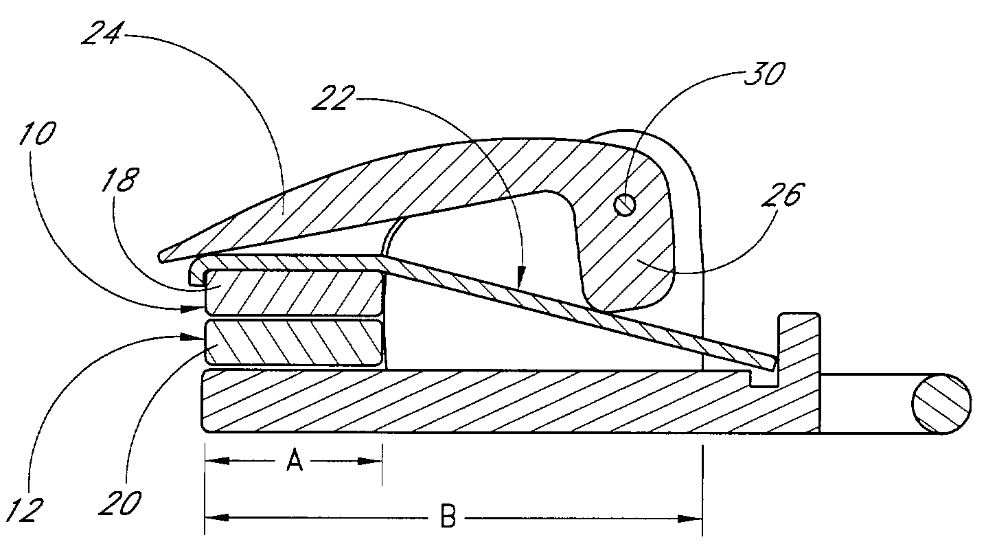
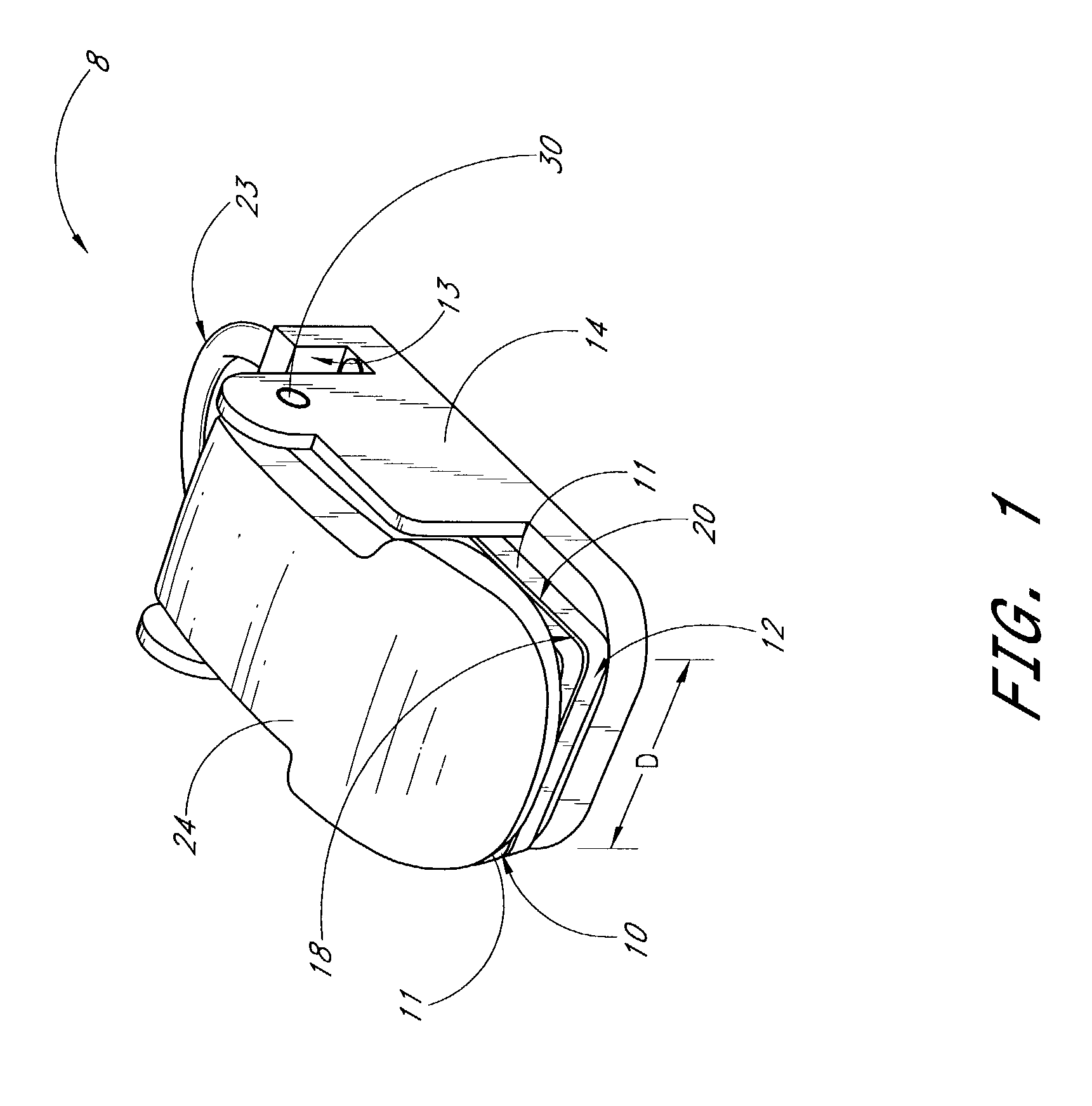
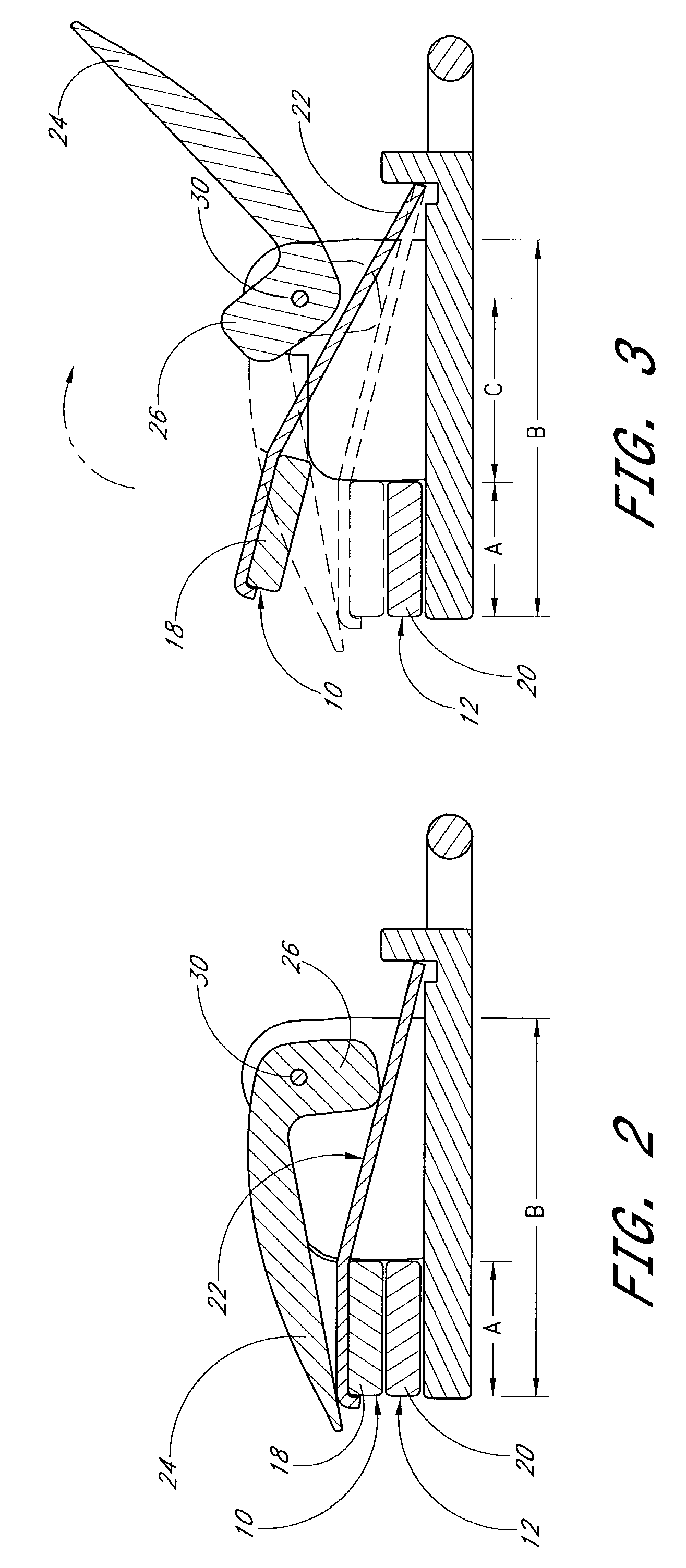
[0017]FIG. 1 depicts one embodiment of the disclosed card attachment 8. The card attachment 8 includes a first jaw 10 and a second jaw 12. The second jaw 12 is substantially fixed while the first jaw 10 moves up and down. The first jaw 10 and the second jaw 12 preferably include gripping pads 11. The first jaw 10 includes a first gripping surface 18 and the second jaw 12 includes a second gripping surface 20. In many preferred embodiments, the gripping surfaces 18 and 20 are the portions of the gripping pads 11 that contact a card 32 as it is grasped by the card attachment 8. The card attachment 8 has a closed position, shown in FIG. 2, in which the jaws are pressed together and an open position, shown in FIG. 3, in which the jaws are spread apart.

[0018]The first jaw 10 and the second jaw 12 have a substantially parallel orientation when closed. In many embodiments, a spring 22 is connected to the first jaw 10 at one end and, at the other end, to the second jaw 12. The second jaw 12...


PUM


Abstract

The present invention relates to a card attachment for holding cards. The jaws of the card attachment can be locking in a closed position to ensure a secure grip on a card. Plastic gripping pads are included to increase the friction between the card and the jaws. Side walls are included to limit the distance a card may be inserted into the card attachment. Limiting the insertion of a card in this manner allows a card to be held without covering large amounts of the card. The ratio of an insertion length to the length of the side wall is selected to allow a card to be held securely without covering excessive amounts of the card. Thus a card can be held without covering pictures, words, or indicia on the card.

Description

BACKGROUND OF THE INVENTION[0001]1. Field of the Invention[0002]The present invention relates to a card attachment that grasps a card or similar object to facilitate use and display of the card.[0003]2. Description of the Related Art[0004]Identification cards, credentials, badges, access cards and similar items are becoming common place in today's society. People are often required to display identification cards, badges, and / or access cards in certain places such as offices, conventions, special events and other secure areas. Typical methods of displaying such cards or badges include a first device such as a neck or wrist lanyard, a clip, or a pin that connect to a users clothing and a second device that retains the card to be displayed. Among the most common devices for retaining a card or badge are clips, key rings, strap clips, and swivel hooks.[0005]Most frequently, clips, key rings, strap clips, and swivel hooks connect with a slot or hole that must be punched in the card. For...

Claims


Application Information

Patent Timeline
Patent Type & Authority Patents(United States)
IPC IPC(8): A44B21/00A45F5/02A44B99/00
CPCA45F5/00A45F5/004A45F2200/055Y10T24/44419Y10T24/44444Y10T24/44427Y10T24/44436Y10T24/44376
Inventor BUETTELL, BRUCE J.
Owner PRECISION DYNAMICS CORPORATION
Why Eureka
Try Eureka