Methods of making microstructured lamina and apparatus

Active Publication Date: 2007-02-13
3M INNOVATIVE PROPERTIES CO
View PDF37 Cites 39 Cited by
  • Summary
  • Abstract
  • Description
  • Claims
  • Application Information

AI Technical Summary

Benefits of technology

[0014]In another embodiment, the invention relates to a fixture for lamina(e) comprising two opposing parallel surfaces connected by a perpendicular base support, said surfaces having an adjustable opening therebetween, a means for retracting and advancing at least one of the opposing surfaces for receipt of a lamina, and a means for kinematically positioning individual laminae. The fixture may optionally comprise a means for verifying the position of the lamina(e). The assembly fixture preferably further comprises a means for maintaining the position of the lamina(e) in the stack. Further, the precision of the position of each lamina relative to an adjacent lamina is at least 0.0001 inches (0.00254 mm).
[0015]For each of these embodiments, the lamina preferably has a thickness ranging from 0.001 inches (0.0254 mm) to 0.020 inches (0.508 mm) and more preferably from 0.003 inches (0.076 mm) to 0.010 inches (0.254 mm). Particularly for such thin laminae, it is preferred that the lamina is kinematically constrained in three degrees of freedom by the machining fixture and/or the assembly fixture such as by kinematic constraint of x translation, z t

Problems solved by technology

Thus, such microsphere-based sheeting has a relatively low sensitivity to the orientation at which the sheeting is placed on a surface.
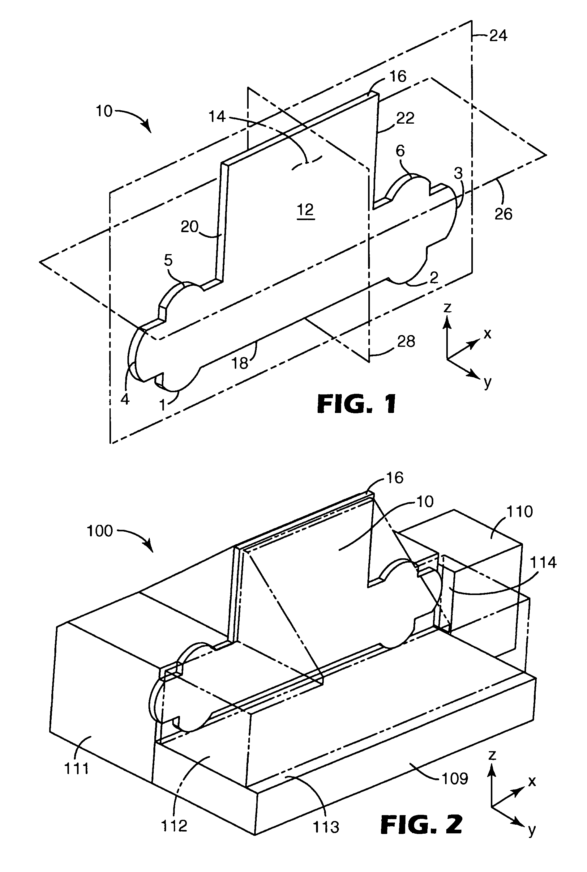
In general, however, such sheeting has

Method used


Image

  • Methods of making microstructured lamina and apparatus
  • Methods of making microstructured lamina and apparatus
  • Methods of making microstructured lamina and apparatus

Examples


Embodiment Construction

[0025]The present invention discloses methods of machining a lamina, methods of assembling laminae forming a master mold, methods of making a laminae, and methods of replicating a master mold comprising a stack of laminae. The invention relates to lamina(e) as well as apparatus useful as fixtures suitable for use in machining and / or assembly of lamina(e). The invention relates to the practice of each of these embodiments alone as well as the practice of the various combinations of such embodiments.

[0026]The method of machining a lamina, method of assembling laminae, the fixture for machining and / or assembling the lamina(e), as well as the lamina, share a common feature of “kinematic positioning”. As described for example in Precision Machine Design, Alexander Slocum, Prentice Hall, Englewood Cliffs, N.J., 1992, p. 352–354, “The principle of kinematic design, states that point contact should be established at the minimum number of points to constrain a body in the desired position an...


PUM

PropertyMeasurementUnit
Thicknessaaaaaaaaaa
Thicknessaaaaaaaaaa
Thicknessaaaaaaaaaa

Abstract

The present invention relates to methods of making microstructured laminae for replication and apparatus. In a preferred embodiment, the invention relates to machining V-shaped grooves on individual lamina forming cube-corner microstructures.

Description

FIELD OF THE INVENTION[0001]The present invention relates to methods of making microstructured lamina for replication and apparatus. In a preferred embodiment, the invention relates to machining V-shaped grooves on an individual lamina forming cube-corner microstructures.BACKGROUND OF THE INVENTION[0002]Retroreflective materials are characterized by the ability to redirect light incident on the material back toward the originating light source. This property has led to the widespread use of retroreflective sheeting for a variety of traffic and personal safety uses. Retroreflective sheeting is commonly employed in a variety of articles, for example, road signs, barricades, license plates, pavement markers and marking tape, as well as retroreflective tapes for vehicles and clothing.[0003]Two known types of retroreflective sheeting are microsphere-based sheeting and cube corner sheeting. Microsphere-based sheeting, sometimes referred to as “beaded” sheeting, employs a multitude of micr...

Claims


Application Information

Patent Timeline
IPC IPC(8): B23P13/04B23P15/24B23Q3/18
CPCB23P15/246B23Q3/18Y10T29/49885Y10T409/30868Y10T29/49996Y10T29/49901Y10T428/24355Y10T29/53961Y10T29/49995Y10T29/53991Y10T83/2037B23H7/02B23P15/24G02B5/124B29C33/30
Inventor SMEENK, LARS A.ANDERSON, CONRAD V.SEWALL, NELSON D.SMITH, KENNETH L.
Owner 3M INNOVATIVE PROPERTIES CO
Why Eureka
Try Eureka