Hotformed hubs and method

a technology of hubs and hot-formed parts, which is applied in the direction of manufacturing tools, semiconductor/solid-state device details, other domestic articles, etc., can solve the problem of relatively large scrap amount created by the process for each component produced, and achieve the effect of improving the part and process, reducing the amount of flashing, and reducing the quantity of flashing

Active Publication Date: 2007-02-13
AMERICAN AXLE & MFG
View PDF15 Cites 0 Cited by
  • Summary
  • Abstract
  • Description
  • Claims
  • Application Information

AI Technical Summary

Benefits of technology

[0002]Automobile and other industrial applications often require suspension or power transmission components to be structurally robust in order to react or transmit relatively high loads. Due to the high load requirements, these parts are often constructed from steel using a forging process. With the cost of steel rapidly increasing in today's market, it has become desirable to reduce the amount of steel scrap generated when manufacturing a steel structural component.
[0006]While the above-described process is useful for manufacturing forged components, improvement in the part and process may be realized. For example, it may be advantageous to produce an irregularly shaped forging having a reduced quantity of flashing. A reduced amount of flashing may reduce the final component cost by reducing the scrap generated during the manufacturing process.
[0007]Furthermore, it may be advantageous to define a process for forging a component having a reduced number of process steps. A reduced number of steps may reduce the complexity and the time required to complete the forging process.
[0008]The forging method of the present invention eliminates the need for a trimming step as previously required and also greatly reduces the quantity of steel converted to scrap during the manufacturing process of forging an irregularly shaped component. Specifically, a method of manufacturing an irregularly shaped forging includes heating a billet to a predetermined temperature, placing the heated billet within a cavity of a die set having a punch and a die, advancing the punch of the die set into the cavity to begin to displace the material into a plurality of radially extending and circumferentially spaced apart extremities of the cavity, and continuing to advance the punch into the die to force a portion of the material to enter predetermined clearance zones between the punch and die. The predetermined clearance zones are circumferentially spaced apart and positioned between the extremities of the cavity to form an irregularly shaped forging pattern having a plurality of axially extending flash sections positioned between radially extending pad sections of the irregularly shaped forging.

Problems solved by technology

While this process is effective to increase the likelihood that the areas of the die cavities including the radially extending protrusions are properly filled, this process creates a relatively large amount of scrap for each component produced.

Method used


Image

  • Hotformed hubs and method
  • Hotformed hubs and method
  • Hotformed hubs and method

Examples


Embodiment Construction

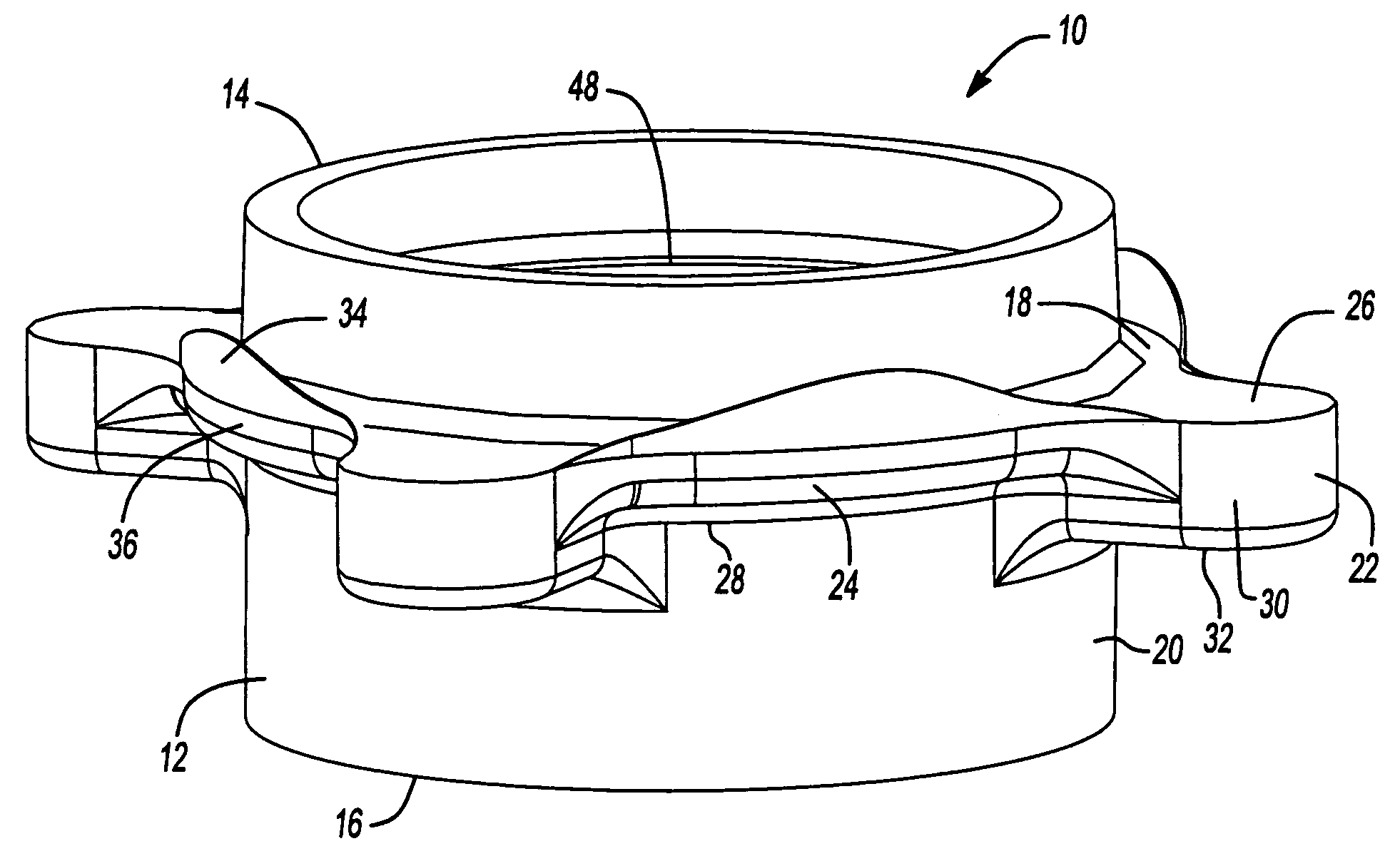
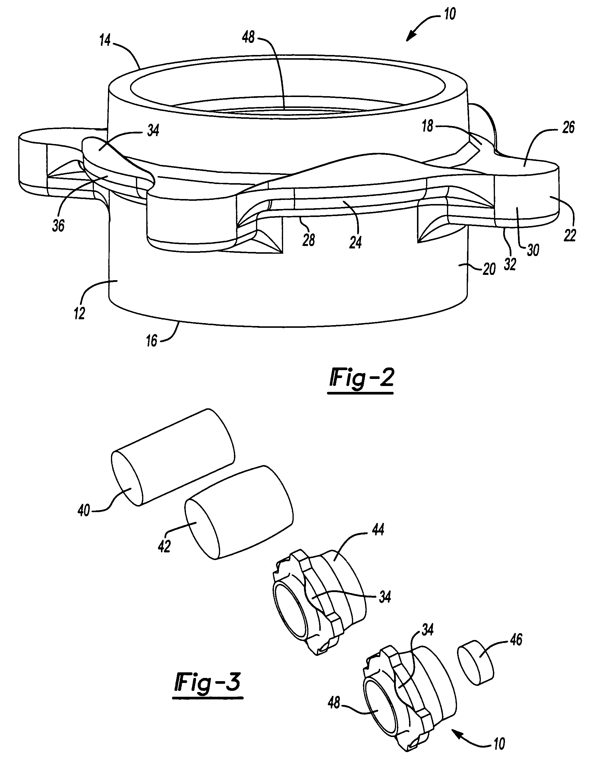
[0016]With reference to FIG. 2, a finish forged hub constructed in accordance with the principles of the present invention is identified at reference numeral 10. Hub 10 is merely an exemplary embodiment irregularly shaped forging useful to illustrate a method of forging irregularly shaped objects. It should be appreciated that any number of forged parts having radially extending and circumferentially spaced apart protrusions are contemplated as being within the scope of the present invention. Therefore, it is emphasized that the scope of the invention is defined by the claims and should not be limited to the configuration of the embodiment described hereinafter.

[0017]Hub 10 includes a substantially cylindrical hollow body 12 having a first end 14 and a second end 16. An integrally formed flange 18 radially outwardly extends from an outer surface 20 of body 12. Radially extending flange 18 is axially positioned between first end 14 and second end 16. Radially extending flange 18 incl...


PUM

PropertyMeasurementUnit
weightaaaaaaaaaa
radial dimensionaaaaaaaaaa
areaaaaaaaaaaa

Abstract

A method of manufacturing an irregularly shaped forging includes heating a billet to a predetermined temperature, placing the heated billet within the cavity of a die, advancing a punch into the cavity to begin to disperse the material into a plurality of radially extending extremities of the cavity and continuing to advance the punch into the die to force a portion of the material to enter predetermined clearance zones between the punch and the die to form an irregularly shaped forging having a plurality of axially extending flash portions.

Description

BACKGROUND AND SUMMARY OF THE INVENTION[0001]The present invention generally relates to a method of forging steel components. More particularly, the present invention relates to hotformed irregularly shaped forgings and a method of forging irregularly shaped components.[0002]Automobile and other industrial applications often require suspension or power transmission components to be structurally robust in order to react or transmit relatively high loads. Due to the high load requirements, these parts are often constructed from steel using a forging process. With the cost of steel rapidly increasing in today's market, it has become desirable to reduce the amount of steel scrap generated when manufacturing a steel structural component.[0003]For certain irregularly shaped components such as hubs, spindles, flanges and gears, previously known forging methods often require subsequent trimming and / or machining operations to remove flash generated during the forging operation. In one exampl...

Claims


Application Information

Patent Timeline
Patent Type & Authority Patents(United States)
IPC IPC(8): B21K23/04B21J5/02
CPCB21J5/00B21J5/02B21K1/40Y10T428/12229Y10T428/12264B21J5/12
Inventor LOWE, JASON J.
Owner AMERICAN AXLE & MFG
Why Eureka
Try Eureka