Air intake device for scooter-type two-wheeled motor vehicle

a two-wheeled motor vehicle and air intake technology, which is applied in the direction of machines/engines, combustion-air/fuel-air treatment, machine equipment, etc., can solve the problems of excessive intake resistance, limitation of engine output, and expansion of the external shape of the air cleaner box, so as to improve the response of the engine

Inactive Publication Date: 2007-02-13
YAMAHA MOTOR CO LTD
View PDF23 Cites 9 Cited by
  • Summary
  • Abstract
  • Description
  • Claims
  • Application Information

AI Technical Summary

Benefits of technology

[0010]The invention was made in view of the situations above, and an advantage thereof is to provide a scooter-type motorcycle intake device which can facilitate the increase in the output of an engine by increasing the displacement thereof while preventing the unnecessary enlargement of the vehicle body of a scooter-type motorcycle.
[0012]According to an embodiment to the present invention, the second air cleaner box can be provided by making use of a dead space defined on the side of the rear wheel. Consequently, the capacity of the air compartment can be increased by the first and second air cleaner boxes while preventing the enlargement of the vehicle body. Thus, there can be provided a scooter-type motorcycle intake device which can facilitate the increase in the output of the engine by increasing the displacement thereof.
[0016]According to the construction, the capacity of the air compartment downstream of the air cleaner element in the first air cleaner box is increased by the capacity of the second air cleaner box. Due to this, since a large amount of air in the air cleaner boxes can be supplied to the engine without any resistance, when the opening of the throttle valve is increased, the response of the engine can be improved.

Problems solved by technology

Incidentally, in the conventional intake device that has been described above, since the capacity of the air cleaner box is small, there has existed a limitation on the attempt to increase the output of the engine by increasing the displacement thereof.
Namely, this is because, when attempting to increase the amount of intake air by increasing the displacement of the engine, the flow of intake air in the air cleaner box gets faster, and this leads to an excessive increase in intake resistance.
While a drawback like this can be resolved by increasing the capacity of the air cleaner box, in the event that this resolution is adopted, the external shape of the air cleaner box is enlarged, whereby there is caused instead a problem that the vehicle body is made larger in size in association with the enlargement of the external shape of the air cleaner box.

Method used


Image

  • Air intake device for scooter-type two-wheeled motor vehicle
  • Air intake device for scooter-type two-wheeled motor vehicle
  • Air intake device for scooter-type two-wheeled motor vehicle

Examples


first embodiment

(First Embodiment)

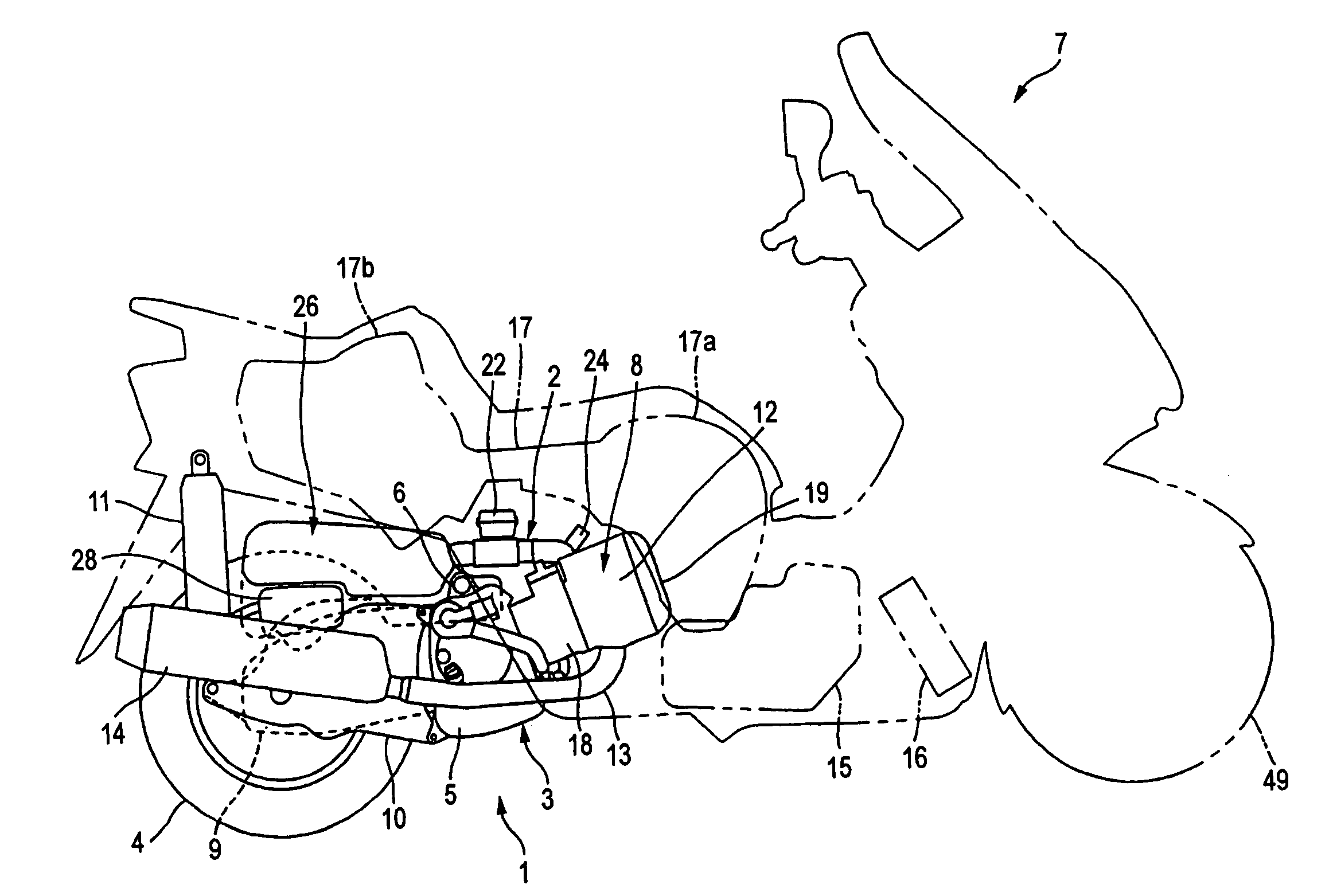
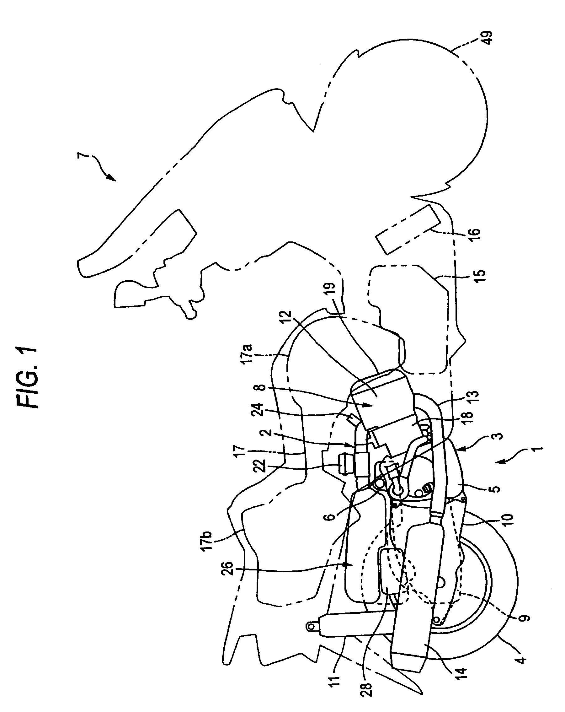
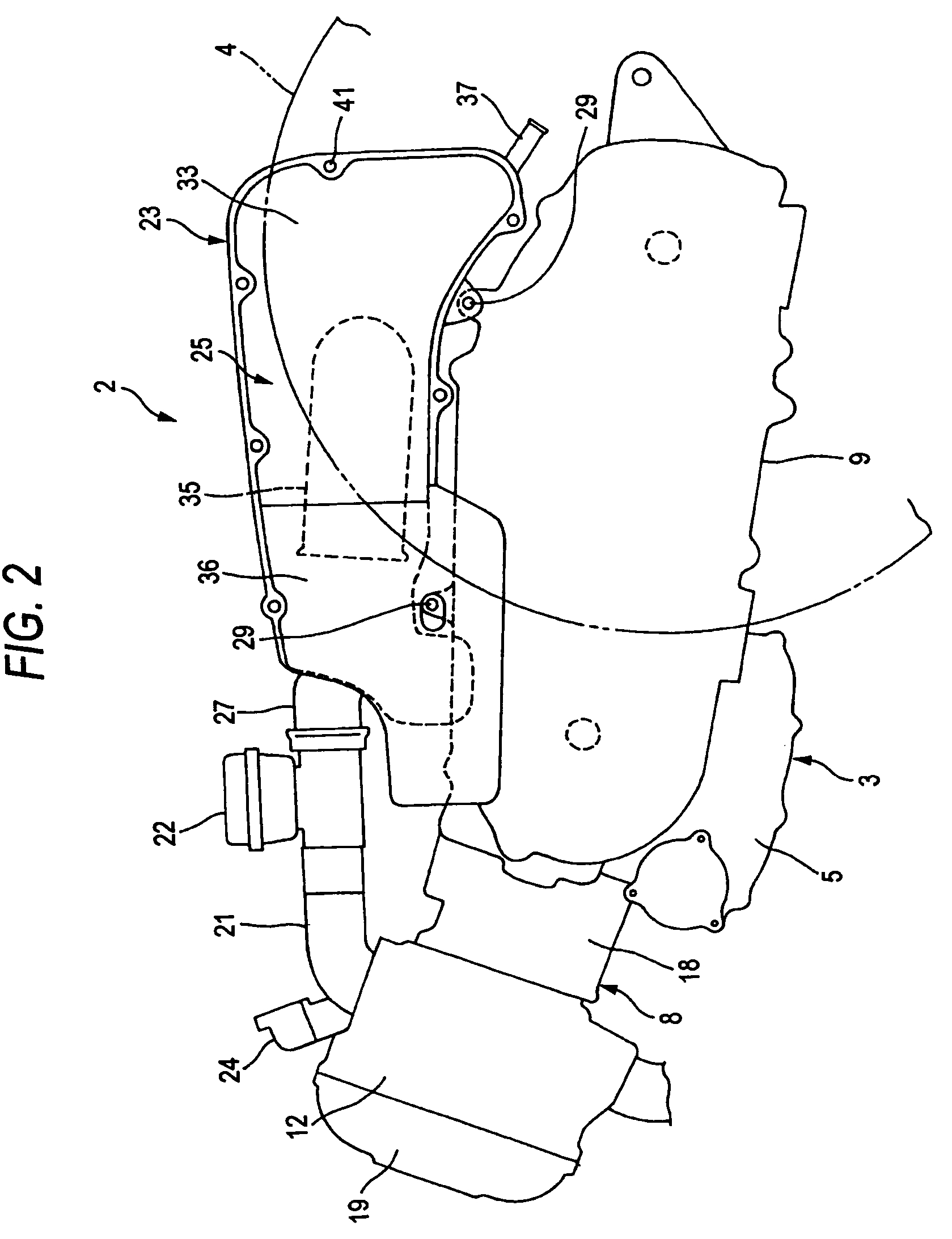
[0024]FIGS. 1 to 4 illustrate a first embodiment.

[0025]In the drawings, reference numeral 1 denotes a unit-swinging power train unit equipped with an intake device 2. This power train unit includes an engine 3 and a rear wheel 4 which are incorporated therein integrally. The power train unit 1 is supported on a vehicle body frame, not shown, of a scooter 7 via a link (not shown) coupled to a coupling boss 6 at an upper end portion of a crankcase 5 of the engine 3 in such a manner as to swing vertically. Note that when used in the following description, left and right indicate transverse directions of the scooter 7 when facing the front of the scooter 7.

[0026]The engine 3 includes the crankcase 5 and a cylinder 8 which protrudes forward and upward from the crankcase 5, and a transmission case 9 which extends in the longitudinal direction is provided on a left-hand side of the rear wheel 4 (refer to FIG. 2). The rear wheel 4 is supported by the transmission case 9 an...

second embodiment

(Second Embodiment)

[0047]FIG. 5 illustrates a second embodiment.

[0048]In an air cleaner 51 shown in FIG. 5, a front portion of a downstream-side box 31 of a first air cleaner box 25 positioned on a left-hand side of the rear wheel extends rightward beyond a center line C of the scooter 7 in the transverse direction thereof, and a second air cleaner box 53 according to the embodiment is connected to a distal end portion of the extending portion 52. Of the first and second air cleaner boxes 25, 53, an air cleaner element 32 is provided only in the interior of the first air cleaner box 25. An intake duct 27 made up of a rubber pipe is attached to a front part of the extending portion 52 at a central portion thereof as viewed in the transverse direction of the scooter 7, and the air cleaner box is connected to a throttle valve 22, not shown, via the intake duct 27. Note that the same construction as that illustrated in FIGS. 1 to 4 is adapted to the other portions of the first air clean...

third embodiment

(Third Embodiment)

[0050]FIG. 6 illustrates a third embodiment.

[0051]As shown in FIG. 6, while an air cleaner 51 according to this embodiment is constructed so as to have substantially the same construction as that of the second embodiment, a rear end portion of a second air cleaner box 53 of this embodiment is made to communicate with a first air cleaner box 25.

[0052]To be more specific, in the air cleaner 51 shown in FIG. 6, the second air cleaner box 53 and the first air cleaner box 25 are connected to each other via a communication pipe 61. This communication pipe 61 extends in the transverse direction of the scooter 7 and is connected to a downstream-side box 31 of the first air cleaner box 25 and a left half portion 55 of the second air cleaner box 53.

[0053]According to the air cleaners 51 according to the second and third embodiments illustrated in FIGS. 5 and 6, the capacity of the downstream-side air compartment 40 positioned downstream of the air cleaner element 32 in the f...


PUM


Abstract

A first air cleaner box (25) is provided on one side of a rear wheel (4) above a transmission case (9) of a unit-swinging power train unit (1), whereas a second air cleaner box (26) is provided on the other side of the rear wheel (9). Air compartments (40) of the air cleaner boxes (25, 26) are connected to a throttle valve (22) while the air compartments of the air cleaner boxes are made to communicate with each other. The second air cleaner box (26) can be provided by making use of a dead space defined on a side of the rear wheel (4). The capacity of the air compartment (40) can be increased by the first and second air cleaner boxes (25, 26) while preventing the enlargement of the vehicle body, whereby the output of an engine (3) can be increased by increasing the displacement of the engine (3).

Description

BACKGROUND OF THE INVENTION[0001]1. Technical Field[0002]The present invention relates to a scooter-type motorcycle intake device in which an air cleaner box is provided on each side of a rear wheel.[0003]2. Background Art[0004]Conventionally, in a scooter-type motorcycle (hereinafter, referred simply to as scooter), a unit-swinging power train unit having an engine and a rear wheel is attached to a vehicle body frame in such a manner as to swing vertically. In a longitudinal direction of the scooter, a front end part of the power train unit is constituted by an engine, and a rear wheel supporting transmission case is attached integrally to a crankcase of the engine. A front end part of the engine is supported on the vehicle body frame in such a manner as to swing, and a rear end part of the transmission case is connected to the vehicle body frame via a cushion unit.[0005]The transmission case is constructed so as to extend longitudinally on a left-hand side of the rear wheel, and p...

Claims


Application Information

Patent Timeline
Patent Type & Authority Patents(United States)
IPC IPC(8): B60K11/00B60K13/02B62J99/00B62K11/00F02M35/16
CPCB62K11/00F02M35/162F02M35/10019B62K2202/00F02M35/02B62J40/10
Inventor SUGITANI, TSUYOSHISUGIYAMA, FUMIYASU
Owner YAMAHA MOTOR CO LTD
Why Eureka
Try Eureka