Radioactive substance container, manufacturing apparatus thereof and manufacturing method thereof

a technology of radioactive substances and manufacturing apparatus, applied in the field of containers, can solve the problems of high friction, metal billet formation, troublesome manufacturing steps, etc., and achieve the effect of less troublesome steps

Inactive Publication Date: 2007-02-13
MITSUBISHI HEAVY IND LTD
View PDF16 Cites 2 Cited by
  • Summary
  • Abstract
  • Description
  • Claims
  • Application Information

AI Technical Summary

Benefits of technology

[0018]In addition, the bottomed container of the invention is suitable for a container in which a ratio (L / Di) of an axial length L to an inner diameter Di is not less than 1 like a cask for storing used nuclear fuel in which an axial length reaches a several meters. Moreover, the present invention may be applied to a canister as a radioactive substance container. When (L / Di) is less than 1, a certain effect is produced, but as (L / D1) becomes larger than 1, the effect according to this invention is produced more remarkably.
[0125]This invention includes the case where the above-mentioned two steps are carried out once so that the metal billet is formed into a final shape. Moreover, the metal billet may be pressurized from above (see FIGS. 21 through 27), or pressurized from below (see FIG. 28). In such a manner the upsetting and the drawing are combined to be used so that an excessive pressure which is required in the backward extrusion forming is not required. For this reason, since the bottomed container can be formed by a normal large-size pressing machine, it is easily manufactured.

Problems solved by technology

For this reason, there arose a problem that the manufacturing requires troublesome steps.
In addition, in the backward extrusion pressing method, the metal billet is formed while high friction is generated between the container and metal billet.
For this reason, a lot of defects such as pockmarks and ribs are generated on an outer surface of the metal billet, and it takes a long time to remove these defects.
Further, in both the Erhardt boring method and the backward extrusion pressing method, when a dimension and a thickness of the container to be formed become large, a pressure which is required for pressing becomes extremely large.
Therefore, in these methods, it was difficult to manufacture a container having large dimension and thickness.

Method used


Image

  • Radioactive substance container, manufacturing apparatus thereof and manufacturing method thereof
  • Radioactive substance container, manufacturing apparatus thereof and manufacturing method thereof
  • Radioactive substance container, manufacturing apparatus thereof and manufacturing method thereof

Examples


first embodiment

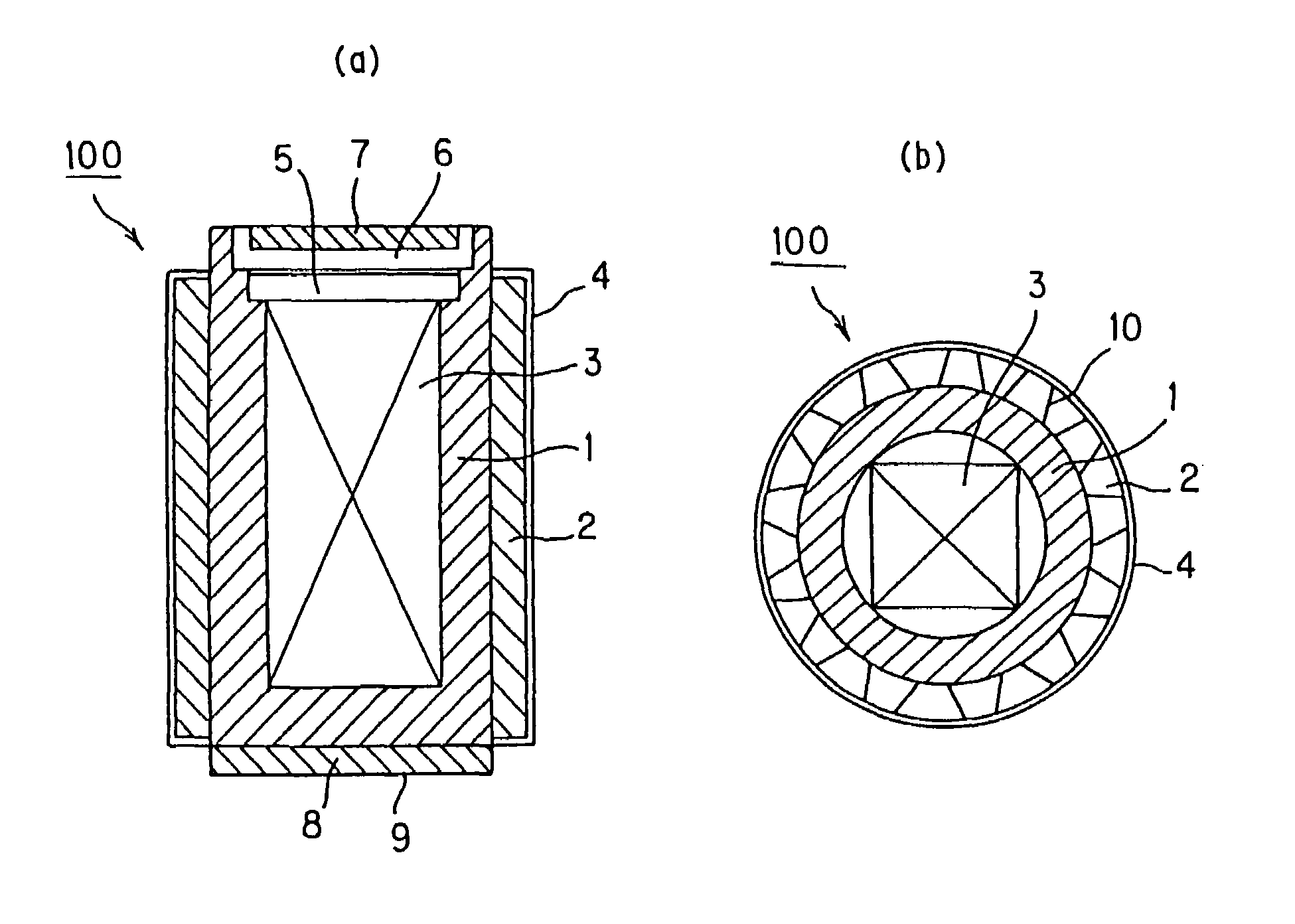
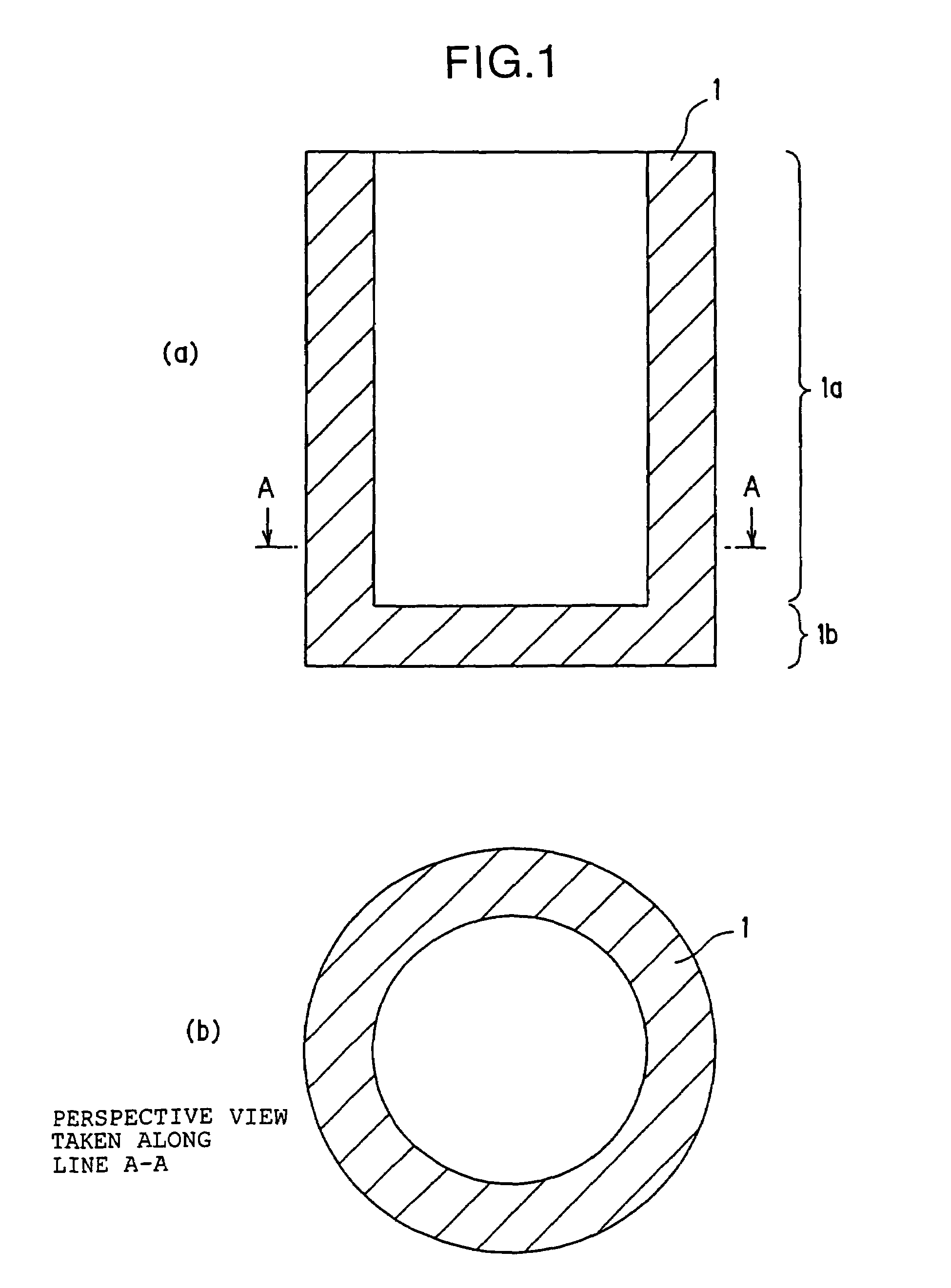
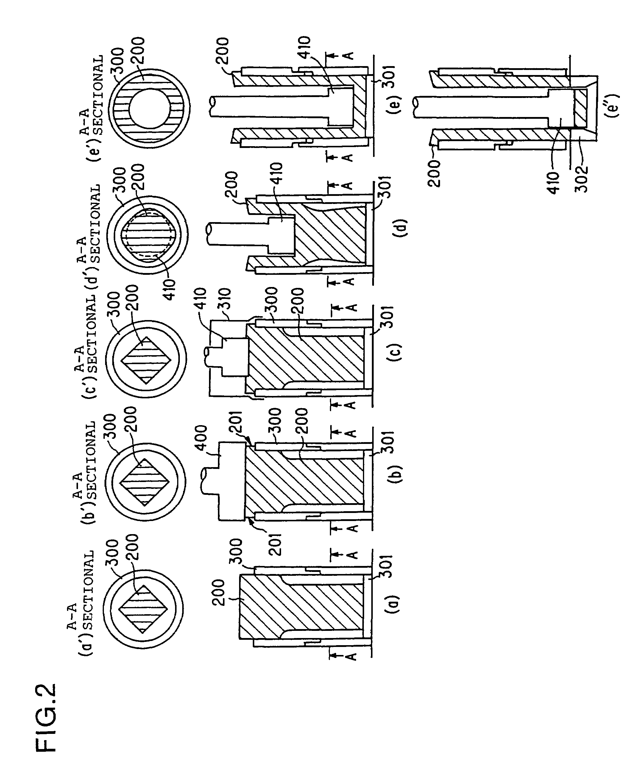
[0160]FIGS. 1(a) and 1(b) are explanatory diagrams showing one example of a bottomed container according to the first embodiment. FIGS. 2(a) through 2(e), 2(a′) through 2(e′) and 2(e″) are explanatory diagrams showing the steps of manufacturing the bottomed container 1 shown in FIGS. 1(a) and 1(b). FIGS. 3(a) through 3(c) are perspective views showing one example of a metal billet 200 to be used in the first embodiment. As shown in FIGS. 1(a), a bottom section 1b of the bottomed container 1 according to the first embodiment is formed integrally with a body section 1a, and as is clear from FIG. 1(b), a sectional form of the bottomed container 1 of the first embodiment is circular.

[0161]In this manufacturing method, the bottomed container 1 is manufactured by a punch according to hot dilation forming. Firstly there will be explained below the metal billet to be used in the manufacturing steps. The metal billet 200 is manufactured by cutting or free forging a foundry molding lump or a ...

second embodiment

[0227]FIG. 13 is a perspective view showing the bottomed container according to a second embodiment of the present invention. The bottomed container 1 shown in FIG. 13 is characterized in that its external shape and internal shape are octagonal. Moreover, at least one of the external shape and the internal shape of the container may be octagonal. Since a basket for supporting a fuel bar aggregate is housed in the bottomed container of the cask as a radioactive substance container, it is preferable that the internal shape of the bottomed container is formed into a shape which matches with the basket particularly in a cask. Therefore, the internal shape of the cask is desirably octagonal instead of circular. Moreover, in the case where the internal shape of the cask is octagonal, since it is advantageous to a dimension and a weight that the thickness of the cask body is uniform as much as possible, it is desirable that the external shape of the cask body is also octagonal. This bottom...

third embodiment

[0231]FIG. 17 is a axially sectional view showing the bottomed container according to a third embodiment. The bottomed container 1 is characterized in that a body and a bottom are formed integrally and a spot facing section is also formed on the bottom of the container. The bottom provided with the spot facing section was conventionally mounted to a thick cylinder by welding, but in the manufacturing method, besides the step of providing the spot facing section on the bottom, the welding step and the heat treating step after the welding are required. For this reason, there arises a problem that the manufacturing requires troublesome steps. According to the method of manufacturing a bottomed container of the present invention, since the bottom provided with the spot facing section can be formed integrally with the body by one step, there is an advantage that the manufacturing becomes very easy.

[0232]FIGS. 18(a) through 18(e), 18(b′), 18(c′) and 18(e′) are explanatory diagrams showing...


PUM

PropertyMeasurementUnit
inner diameteraaaaaaaaaa
thicknessaaaaaaaaaa
thicknessaaaaaaaaaa

Abstract

In the metal billet to be used for hot dilation forming, a forward side with respect to the pressing direction has a quadrate section and its diagonal length is not more than an inner diameter of a container. Moreover, a backward side with respect to the pressing direction has a circular section and its diameter is substantially same as the inner diameter of the container. The metal billet is heated to a temperature suitable for press working and is set into a container for press forming. While a center of a workpiece of the metal billet is being bored by a boring punch to be operated by a pressing machine, the metal billet is hot-dilated so that a bottomed container for a cask is formed.

Description

CROSS-REFERENCE TO RELATED APPLICATIONS[0001]This application is a Divisional of application Ser. No. 09 / 926,811, filed Jul. 1, 2002, currently pending, the contents of which are herein incorporated by reference in their entirety.TECHNICAL FIELD[0002]The present invention relates to a container having thick walls (“thick container”) such as a cask for housing, transporting and storing used nuclear fuel aggregate and substance contaminated by radioactivity, for example. Particularly this invention relates to a thick container in which a body section and a bottom section are formed integrally, or a thick drum which can be used as a cylinder of a large size pressing machine, or a canister for storing substance contaminated by radioactivity. The invention relates to a container or a drum which requires less troublesome steps for manufacturing and has an excellent end surface form, a manufacturing apparatus thereof and a manufacturing method thereof.BACKGROUND ART[0003]As a cylinder or t...

Claims


Application Information

Patent Timeline
Patent Type & Authority Patents(United States)
IPC IPC(8): G21K5/00B21C1/26B21C23/01B21C23/20B21J5/10B21J9/04B21K21/06G21C19/32G21F5/00G21F5/008
CPCB21C1/26B21C23/01B21C23/205B21J5/10B21J9/04G21C19/32G21F5/00G21F5/008B21K21/06G21Y2004/305G21Y2002/302Y02E30/30
Inventor FUNAKOSHI, YOSHIHIKOTSUNEZUMI, TAKESHIMIZUNO, NAOHIROTOKUNO, KATSUHIKOMATSUMOTO, CHIKAYUKITAURA, YOSHIHARUSHIROGANE, SHIGENORIOHSONO, KATSUNARIMATSUOKA, TOSHIHIRO
Owner MITSUBISHI HEAVY IND LTD
Why Eureka
Try Eureka