
Energy management apparatus and method for injection molding systems

a technology of energy management apparatus and injection molding machine, which is applied in the direction of total factory control, programme control, electric controller, etc., can solve the problems that injection molding machines have not been used widely, and achieve the effects of reducing process demands, reducing overlap motion, and lowering speed profiles

Active Publication Date: 2007-02-13
HUSKY INJECTION MOLDING SYST LTD
View PDF28 Cites 49 Cited by
  • Summary
  • Abstract
  • Description
  • Claims
  • Application Information

AI Technical Summary

Benefits of technology

[0043]It is an advantage of the present invention to be able to reduce the process demands by the machine controller, by either changing process steps to reduce overlapping motions or lowering the speed profiles, to ensure the installed power is not exceeded. This is a novel feature which will enable a series of products with identical functionalities but different levels of performances, according to the installed power (compared to autos with V6 or V8 engines). The advantages of the present invention will also enable the use of extruder heaters to absorb the regenerative energy during screw deceleration. This makes sense because, during the screw deceleration, the heating power to the resin produced by the screw is reduced and regenerative power by the screw can be re-used by the heaters to maintain a uniform heating power to the melted resin.
[0044]It is another advantage of the present invention to be able to eliminate those braking resistors, which are installed for the sole purpose of dissipating the regenerated power during rapid deceleration of an electric motor driven actuator. It is another advantage of the present invention to be able to achieve a lean supply to the hybrid injection molding system by limiting the supply of excess energy, which cannot be used to perform useful work. It is another advantage of the present invention to be able to re-use regenerated power to perform useful work.
[0045]It is a further advantage of the present invention to be able to improve energy efficiency and functional performance while keeping the cost of the system low.
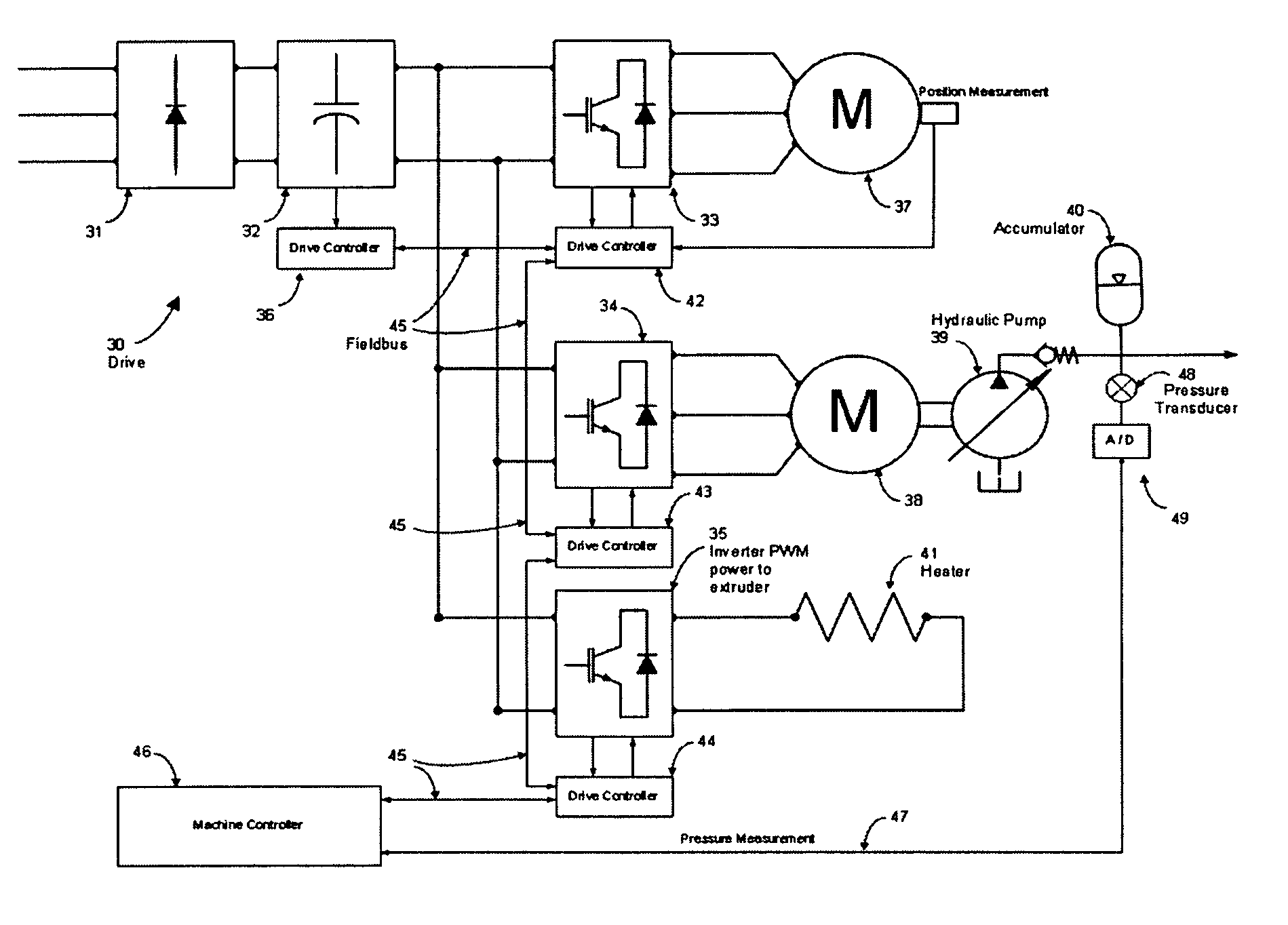
[0046]The above-described advantages, in addition to other advantageous features of this invention, are achieved in another aspect of the present invention by a hybrid injection molding system including a machine controller having structure configured to communicate in real-time with the system's sensors, transducers, actuators, and distributed controllers, to receive signals and measurements from the system and to use such information together with preprogrammed control software to generate command signals and information in real-time to the system and to the system control operations and processes. A common DC link provides DC power to inverters for controlling power to and from at least two electrical motors controlled by adjustable speed drives. A high speed bi-directional communication fieldbus is configured to be capable of communicating to and from all drive controllers and the machine controller. A slave axis is configured to be capable of supplying and absorbing power from the common DC link. A torque controller is configured to be capable of controlling the slave axis in (i) normal speed control and (ii) DC link voltage control, and switching control between the said two controls in a bumpless transfer manner. An electrically driven prime mover of a hydraulic pumping assembly is configured to be capable of regulating the flow rate and the power of the hydraulic fluid supply via the hydraulic driven actuation structure. An energy accumulation means is operable to store and release energy through receipt and release of hydraulic fluid.
[0047]The above-described advantages, in addition to other advantageous features of this invention, may also achieved in yet another aspect of the present invention by an all-electric injection molding system including a machine controller having configured to communicate in real-time with the system's sensors, transducers, actuators, and distributed controllers, for receiving signals and measurements from the system and to use such information together with preprogrammed control software to generate command signals and information in real-time to the system and the system control operations and processes. A common DC link is configured to provide DC power source to inverters for controlling power to and from at least two electrical motors controlled by adjustable speed drives. A high speed bi-directional communication fieldbus is configured to be capable of communicating to and from all drive controllers and the machine controller. A slave axis is configured to be capable of supplying and absorbing power from the common DC link. A torque controller is configured to be capable of controlling the slave axis in (i) normal speed control and (ii) DC link voltage control, and switching control between the two controls in a bumpless transfer manner. An electrically driven high speed motor drives a mechanical flywheel and is capable of regulating the speed of the mechanical flywheel energy accumulation structure is configured to store and release energy through the regulation of the speed of the mechanical flywheel.
[0048]According to a yet another aspect of the present invention, a unique combination of structure and / or steps are provided for an injection molding machine energy management control apparatus including a first electrically-driven prime mover configured to drive at least a first molding machine device, and a second electrically-driven prime mover configured to drive at least a second molding machine device. A common DC link is configured to provide DC energy to the first electrically-driven prime mover and to the second electrically-driven prime mover. A slave axis is configured to supply and absorb energy to / from the common DC link. A machine controller is configured to (i) communicate with the first electrically-driven prime mover, the second electrically-driven prime mover, the common DC link, and the slave axis, (ii) cause the slave axis to supply energy to the common DC link in response to input from at least one of the first electrically-driven prime mover and the second electrically-driven prime mover, and (iii) cause the slave axis to absorb energy from the common DC link in response to input from at least one of the first electrically-driven prime mover and the second electrically-driven prime mover.

Problems solved by technology

DTC also provides excellent torque control but has not been commonly used in injection molding machines.

Method used


Image

  • Energy management apparatus and method for injection molding systems
  • Energy management apparatus and method for injection molding systems
  • Energy management apparatus and method for injection molding systems

Examples


Embodiment Construction

1. Introduction

[0058]The present invention will now be described with respect to several embodiments in which injection molding system actuators are controlled with processing structure, a common DC link, and energy management structure. However, the present invention may find use in other applications such as product handling robots, packaging machines, die-casting machines, metal injection machines, automation equipment, and blow molding machines, where a plurality of electric servo driven actuators are used.

2. Voltage Source Inverter Drive

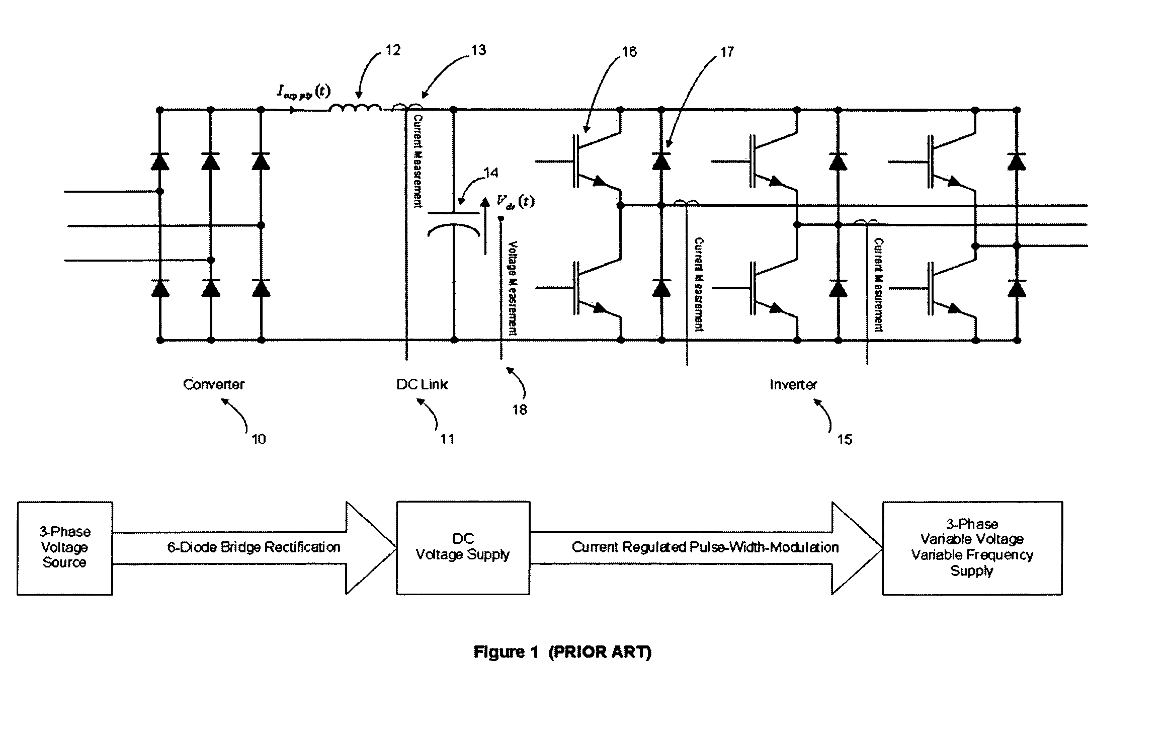
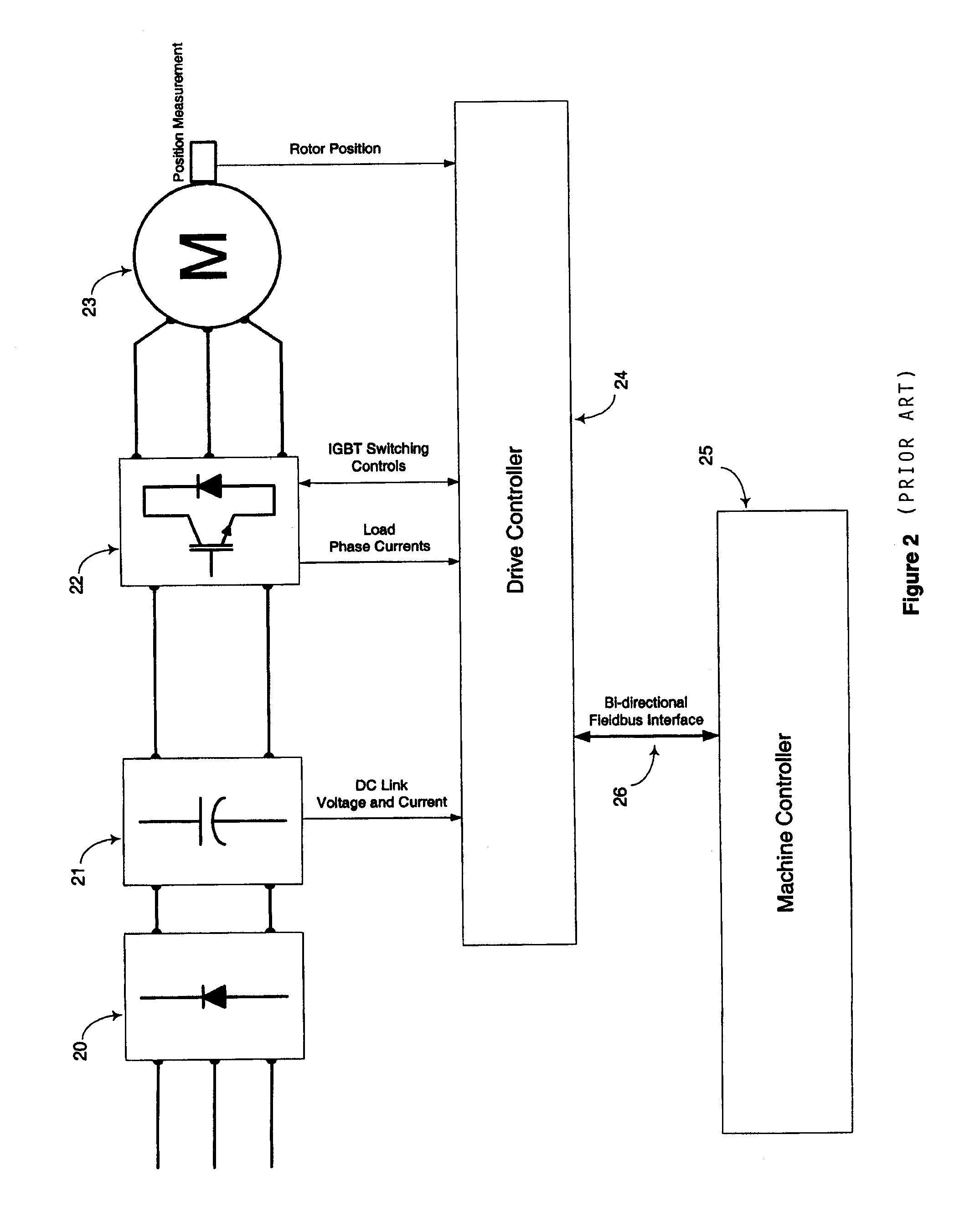
[0059]FIG. 1 shows the main functional parts of a typical VSI drive unit. The VSI takes three-phase power at fixed voltage and frequency, provided from a utility, and converts it to three-phase power at the desired variable voltages and frequencies for use in an adjustable speed electric motor. The unit has three main functional sections. A converter 10 takes the three-phase supply power and, by means of its full wave six-diode bridge, rectifies...


PUM

PropertyMeasurementUnit
DC energyaaaaaaaaaa
absorb energyaaaaaaaaaa
speedaaaaaaaaaa

Abstract

An energy management control apparatus for a molding machine that includes a first electrically-driven prime mover configured to drive at least a first molding machine device, and a second electrically-driven prime mover configured to drive at least a second molding machine device, includes a common DC link configured to provide DC energy to the first electrically-driven prime mover and to the second electrically-driven prime mover. A slave axis is configured to supply and absorb energy from to / from the common DC link. A machine controller is configured to (i) communicate with the first electrically-driven prime mover, the second electrically-driven prime mover, the common DC link, and the slave axis, (ii) cause the slave axis to supply energy to the common DC link in response to input from at least one of the first electrically-driven prime mover and the second electrically-driven prime mover, and (iii) cause the slave axis to absorb energy from the common DC link in response to input from at least one of the first electrically-driven prime mover and the second electrically-driven prime mover.

Description

BACKGROUND OF THE INVENTION[0001]1. Field of the Invention[0002]The present invention relates to an injection molding system and, more particularly, to: the energy management of a hybrid injection molding system that comprises (i) an electrically driven prime mover of a hydraulic pumping assembly and (ii) a plurality of hydraulic and / or electric driven actuators (such as parts handling robots, extruders, injection units, mold stroke, and clamping units, and the like); and to the energy management of an all-electric injection molding machine system that comprises a plurality of electric driven actuators (such as parts handling robots, extruders, injection units, mold stroke and clamping units, and the like).[0003]2. Description of Related Art[0004]Actuators and of conventional injection molding machines typically use a hydraulic power source. It is well known that hydraulic systems are not energy efficient. This is primarily due to its inherent volumetric losses and torque losses. Vo...

Claims


Application Information

Patent Timeline
Patent Type & Authority Patents(United States)
IPC IPC(8): G05B11/32B29C45/76B29C45/82
CPCB29C45/7666G05B2219/45244B29C2045/7673B29C2045/824B29C2945/76006B29C2945/76033B29C2945/76083B29C2945/7611B29C2945/76307B29C2945/76454B29C2945/76498B29C2945/76511B29C2945/76518B29C2945/76525B29C2945/76531B29C2945/76545B29C2945/76595B29C2945/76785B29C2945/76876B29C2945/76936B29C2945/76966G05B2219/31135G05B2219/32021G05B2219/34403B29C2045/1792Y02P70/10Y02P80/10Y02P90/02
Inventor CHOI, CHRISTOPHER WAI-MING
Owner HUSKY INJECTION MOLDING SYST LTD
Learn More