Thermal treatment device

A heat treatment device and technology for heating devices, which are applied in heat treatment equipment, quenching devices, manufacturing tools, etc., can solve problems such as the service life of salt media affecting the quenching effect of components, and the failure of salt media to meet the cooling requirements, so as to avoid boiling or quenching. The effect of denaturation, simple structure and uniform heating power

Inactive Publication Date: 2017-03-08
黄鸣
View PDF0 Cites 0 Cited by
  • Summary
  • Abstract
  • Description
  • Claims
  • Application Information

AI Technical Summary

Problems solved by technology

[0004] For the above-mentioned existing salt bath furnaces, when the volume of a single component itself is large or the number of components is large, the high initial temperature of the component or the requirements of the quenching process may require the component to obtain a relatively rapid cooling, but the purely molten salt medium Generally, the above-mentioned cooling requirements cannot be met, and the above technical problems directly affect the quenching effect of the components and the service life of the salt medium. The present invention provides a heat treatment device

Method used


Image

  • Thermal treatment device
  • Thermal treatment device

Examples


Embodiment 1

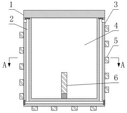
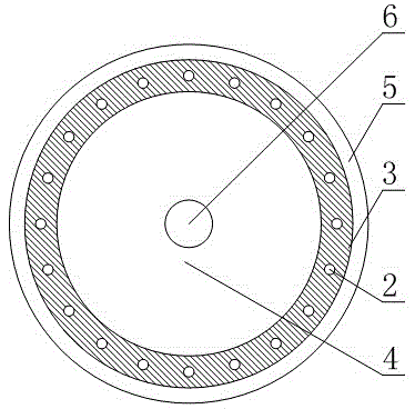
[0021] Such as figure 1 and figure 2 As shown, a heat treatment device includes a bath body 3, the bath body 3 is a barrel-shaped structure provided with a furnace 4, the bath body 3 is also provided with a heating device for heating the furnace 4, and the heating device It includes a mixing electrode 6 arranged in the furnace 4 and an electric heating belt 5 wound on the outside of the side surface and the outside of the bottom surface of the bath body 3 , and a cooling channel 2 is drilled in the tank wall of the bath body 3 .

[0022] In this embodiment, by using the electric heating belt 5 as the heating device, and the heating belt is arranged on the outside of the bath body 3, compared with the existing heating device arranged inside the furnace 4, the heating device is not used in the furnace 4 for salt. The heating medium of the bath is in direct contact, and at the same time, the bath body 3 is used as an intermediate heat transfer object between the heating belt an...

Embodiment 2

[0024] The present embodiment is further limited on the basis of embodiment 1, as figure 1 and figure 2 As shown, as a form of cooling channel 2 that is easy to process, the cooling channel 2 includes two vertical channels arranged on the side of the bath body 3 and a horizontal channel arranged on the bottom surface of the bath body 3, and the two vertical channels pass through the horizontal channel. The channels are connected.

[0025] As a form of cooling flow channel that facilitates uniform temperature drop, there is more than one cooling flow channel.

[0026] In order to further optimize the above-mentioned uniform cooling effect, the vertical channels are evenly distributed in a ring shape on the bath body 3 .

[0027] In order to facilitate the temperature detection or control of the heating medium in this structure, a temperature sensor is also arranged in the furnace 4 .

[0028] In order to reduce or avoid oxidation of the heating medium during the working pro...


PUM


Abstract

The invention discloses a thermal treatment device. The thermal treatment device comprises a bath body which is of a barrel-shaped structure provided with a hearth. A heating device for heating the hearth is further arranged on the bath body and comprises a uniform mixing electrode which is arranged in the hearth and electric heating strips which wind the outer side of the side face of the bath body and the outer side of the bottom surface, and cooling channels are further drilled in the bath wall of the bath body. The thermal treatment device disclosed by the invention is simple in structure, the hearth is uniformly heated and local high temperature is avoided conveniently, and meanwhile, the thermal treatment device further has the characteristics of being quick to raise the temperature, good in controllability of quenching speed for special use, safe to use and capable of automatically balancing the temperature in the depth direction of the hearth and the like.

Description

technical field [0001] The invention relates to the field of heat treatment of mechanical engineering metal materials, in particular to a heat treatment device. Background technique [0002] Metal heat treatment is to heat a metal workpiece in a certain medium to a suitable temperature, and keep it at this temperature for a certain period of time, and then cool it in a different medium at different speeds, by changing the surface or internal microstructure of the metal material A process in which the structure is used to control its performance. The medium for isothermal quenching and graded quenching usually uses salt medium. According to the specific quenching temperature, the above salt medium can be sodium chloride, potassium chloride, barium chloride, sodium cyanide, potassium cyanide, sodium nitrate, nitric acid One or more of salts such as potassium. As the cooling medium, the salt medium not only has low purchase cost of quenching materials, but also has good fluid...

Claims


Application Information

Patent Timeline
Patent Type & Authority Applications(China)
IPC IPC(8): C21D1/62C21D1/34
Inventor 黄鸣
Owner 黄鸣
Why Eureka
Try Eureka