Motor control apparatus

a motor control and motor technology, applied in the direction of motor/generator/converter stopper, dynamo-electric gear control, motor/generator/converter stopper, etc., can solve the problems of increasing signal degradation and signal delay, affecting the accuracy of harmonic current control, and not being able to extract the respective components separately. , to achieve the effect of simple circuitry, simple processing, and accurate control

Inactive Publication Date: 2007-02-13
DENSO CORP
View PDF24 Cites 43 Cited by
  • Summary
  • Abstract
  • Description
  • Claims
  • Application Information

AI Technical Summary

Benefits of technology

[0007]The present invention has been devised in view of the above problems, and an object of the invention is to provide a motor control apparatus having excellent harmonic current control performance, that has a simple circuit configuration and circuit processing while, at the same time, achieves an improved control accuracy.
[0022]In a preferred mode, the harmonic current component of a prescribed order to be superimposed on the polyphase AC current by the harmonic control circuit block is chosen to have an amplitude and phase that reduces the magnetic noise of the polyphase AC rotary electric machine. That is, by superimposing the harmonic current on the polyphase AC current to be fed to the polyphase AC rotary electric machine, a vibration (especially, radial vibration) having a prescribed harmonic order relationship to the superimposed harmonic current can be induced in the core of the polyphase AC rotary electric machine; therefore, by adjusting the phase and amplitude of the vibration induced by the superimposed harmonic current, it becomes possible to reduce the amplitude of the resultant vibration resulting from the combination of the vibration induced by the superimposed harmonic current and the vibration having the same harmonic order and generated in the core before the superimposition of the harmonic current. Accordingly, the magnetic noise generated by the resultant vibration can be reduced to a lower level than the level before the superimposition of the harmonic current.

Problems solved by technology

However, the harmonic current control that uses the motor control described in the above-cited Japanese Unexamined Patent Publications No. 2002-247899 and No. 2002-223600 has had the shortcoming that not only is the circuit configuration complex but, also, the coordinate conversion process is complicated, leading to an increased signal degradation and signal delay and hence, a degradation of the accuracy of the harmonic current control.
Furthermore, with the harmonic current control that uses the motor control described in the above-cited Japanese Unexamined Patent Publications No. 2002-247899 and No. 2002-223600, when components, such as the seventh harmonic current and the fifth harmonic component having a reverse phase order from it, are contained simultaneously that have the same frequency when converted to a first-order dq coordinate system, it has not been possible to extract the respective components separately.

Method used


Image

  • Motor control apparatus
  • Motor control apparatus
  • Motor control apparatus

Examples


embodiment 1

(Embodiment 1)

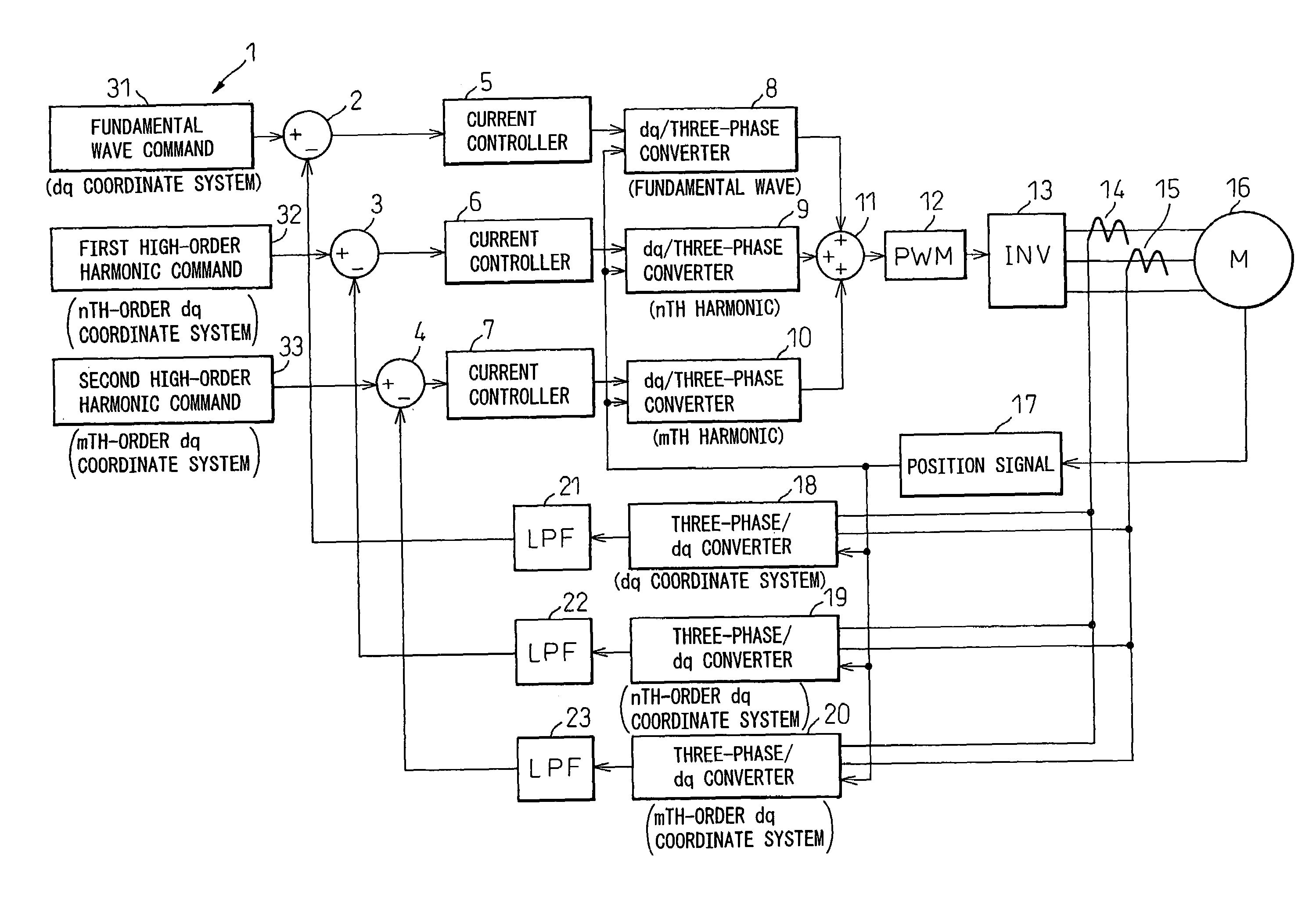
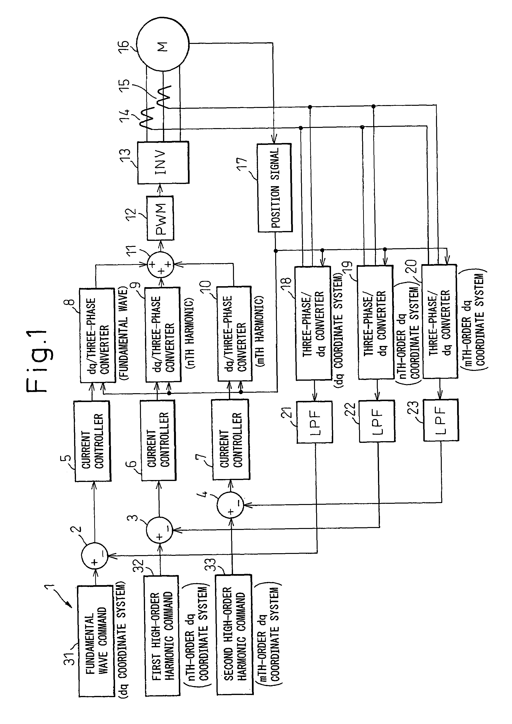
[0037]A first embodiment will be described with reference to the block circuit diagram shown in FIG. 1.

(Configuration)

[0038]In FIG. 1, reference numeral 1 is an electric current commanding section, 2 to 4 are subtractors, 5 to 7 are PI amplifiers, 8 to 10 are dq / three-phase coordinate converters, 11 is an adder, 12 is a PWM voltage generating circuit, 13 is a three-phase inverter, 14 and 15 are current sensors for detecting two phase currents, 16 is a three-phase synchronous motor, 17 is a position signal processor for extracting a signal corresponding to a rotation angle θ from the rotation angle signal output from a rotation angle sensor (not shown) such as a resolver that detects the rotation angle of the three-phase synchronous motor 16, 18 to 20 are three-phase / dq coordinate converters, and 21 to 23 are low-pass filters whose cut-off frequencies are lower than several hundred Hertz.

[0039]The electric current commanding section 1 is a circuit that outputs an electr...

experimental example

[0117]An FEM analysis for the reduction of the magnetic noise was performed using the three-phase synchronous machine (8-pole, 24-slot, IPM) shown in FIG. 10. The fundamental frequency component of the stator current was set to 70 A, and the rotor phase angle was set so as to maximize the torque; in this condition, the radial vibration controlling harmonic currents computed by the above method were superimposed, that is, first only the fifth harmonic current having an amplitude 3A and a reserve phase order from that of the fundamental wave was superimposed, and then, in addition to that, the seventh harmonic current having an amplitude 1A and the same phase order as that of the fundamental wave was superimposed, for comparison with the case where no radial vibration controlling harmonic currents were superimposed. The waveforms of the resulting radial magnetic excitation forces are shown in FIG. 11, and their spectra are shown in FIG. 12. As can be seen, by superimposing the fifth h...


PUM


Abstract

An object of the present invention is to provide a motor control apparatus having excellent harmonic current control performance, that can simplify circuit configuration and circuit processing while, at the same time, achieving improved control accuracy. To achieve this object, detected motor currents are converted by coordinate converters 19 and 20 into an nth-order dq-axis signal and an mth-order dq-axis signal, and their DC components are extracted by low-pass filters 22 and 23; then, the differences of the DC components relative to respective command values are converted back into three-phase AC signals to control the motor currents.

Description

[0001]This application is a continuation of International Application No. PCT / JP2005 / 007365, filed on Apr. 12, 2005.TECHNICAL FIELD[0002]The present invention relates to a motor control apparatus having an excellent harmonic current control performance.BACKGROUND ART[0003]As is well known, in a polyphase AC rotary electric machine, harmonic currents must be controlled properly because the efficiency and output of the motor drops, and the torque ripple increases, if the space harmonics of the magnetic flux are large. Motor controls for selectively controlling the harmonic current components contained in the motor current are disclosed in Japanese Unexamined Patent Publications No. 2002-247899 and No. 2002-223600.[0004]Japanese Unexamined Patent Publications No. 2002-247899 and No. 2002-223600 each propose a motor control apparatus which extracts a harmonic current component by high-pass filtering a first-order dq signal of the motor current, and controls the harmonic current through ...

Claims


Application Information

Patent Timeline
Patent Type & Authority Patents(United States)
IPC IPC(8): H02P27/04H02P21/00H02P6/10H02P21/05H02P21/22H02P23/04H02P27/08
CPCH02P29/0038H02P29/50
Inventor WAKABAYASHI, KENICHIYOSHINAGA, SOICHI
Owner DENSO CORP
Why Eureka
Try Eureka