Electric motor drive

a technology of electric motors and motor drives, applied in the direction of synchronous motors, ac motor stoppers, single network parallel feeding arrangements, etc., can solve the problems of limited service life, noise produced by the operation of contactors, and need regular maintenance, so as to eliminate mechanical contactors, improve reliability, and eliminate noise problems

Inactive Publication Date: 2007-02-13
KONE CORP
View PDF12 Cites 19 Cited by
  • Summary
  • Abstract
  • Description
  • Claims
  • Application Information

AI Technical Summary

Benefits of technology

[0013]The most important advantage of the invention is that the electric motor drive can be implemented without contactors, i.e. without mechanical switching elements. This means an improvement in reliability because the electric motor drive no longer has any moving switching elements subject to wear; these are replaced with electronic circuits and / or components. The invention provides the advantage of eliminating the noise problem caused by mechanical contactors. The invention has the advantage that the elimination of mechanical contactors allows savings to be achieved in installation and maintenance costs.
[0014]The invention also has the advantage that the operating temperature of the electric motor drive can be clearly increased, most preferably from the earlier limit of 20° C. up to 100° C. The size of the cooling elements can be reduced, which leads to savings in space and costs.
[0015]A further advantage of the invention is that a low-value capacitor, e.g. 50 μF, is used in the intermediate circuit of the frequency converter. These capacitors are plastic or paper capacitors, which are durable and cheap. The capacitors previously used in this circuit are wet high-value capacitors, typically 1000 μF, of electrolytic construction. These components are subject to wear and have to be renewed relatively often.
[0016]As for the other advantages of the invention, the following general remarks apply. The harmonic distortion of the electric motor drive can be reduced because the value of the intermediate circuit capacitor is clearly reduced as compared with prior art. In addition, dynamic braking of the electric motor is made possible without any additions to the technical equipment. Dynamic braking is based on a new arrangement for controlling the inverter in the most preferred embodiment of the invention.

Problems solved by technology

A problem with the use of contactors 4, 5 is that they require regular maintenance and that they have a limited service life (e.g. 2 years).
An additional drawback is the noise produced by the operation of the contactors, which is generated by the fast movement and sudden stopping of the connection elements of the contactor.
Further problems result from electromagnetic disturbances of the contactors.
The contactors also increase the price of the electric motor drive.
A drawback with the electric motor drive according to the aforesaid EP application is that it only provides a partial solution to the contactor problems described above.

Method used


Image

  • Electric motor drive
  • Electric motor drive
  • Electric motor drive

Examples


Embodiment Construction

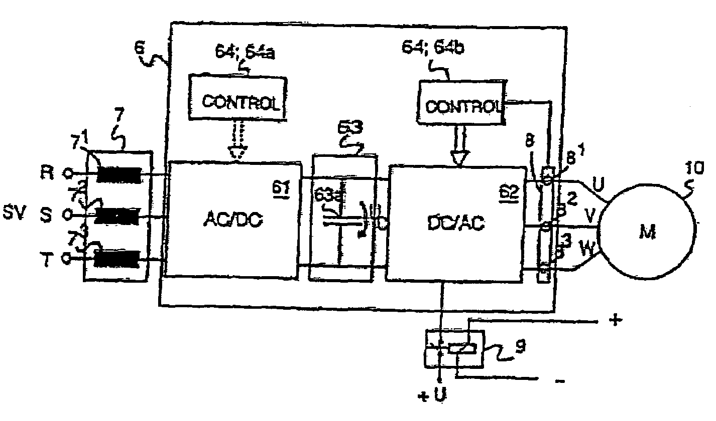
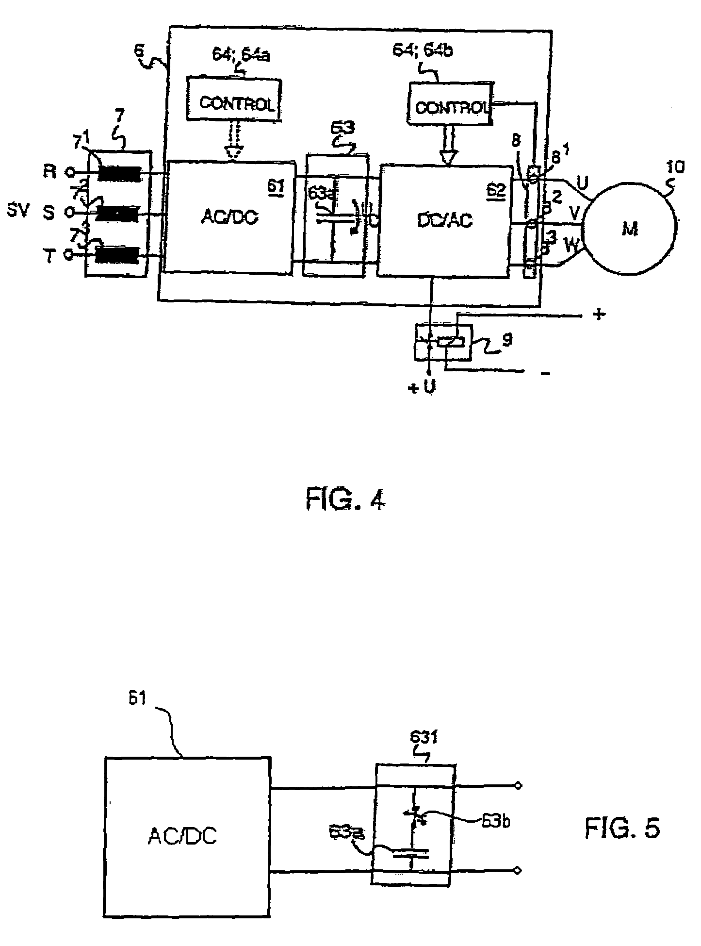
[0026]An electric motor drive according to the invention is visualized in FIG. 4. The electric motor drive is used for regulating and controlling an alternating-current motor, in the present case a three-phase synchronous motor 10. The electric motor drive comprises a frequency converter 6, which again comprises a rectifier 61 and an inverter 62. The rectifier 61 and the inverter 62 are connected to each other via a suitable intermediate circuit 63. The input of the rectifier 61 is connected to an alternating-current power source, such as a three-phase power source, e.g. to an electric network SV, via an inductor unit 7. The inductor unit 7 comprises an inductor 71, 72, 73 connected to each phase R, S, T. The rectifier 61 preferably consists of a bridge implemented using semiconductor switches, such as e.g. the bridge presented in FIG. 2. The output of the rectifier 61 is connected to the intermediate circuit 63. The intermediate circuit 63 comprises at least a capacitor 63a connect...


PUM


Abstract

The invention relates to an electric motor drive for operating an alternating-current motor. The electric motor drive comprises a frequency converter for controlling the motor, which frequency converter comprises a rectifier and an inverter implemented using semiconductor switches arranged in a bridge, and an intermediate circuit placed between the rectifier and the inverter and comprising a capacitor. According to the invention, the electric motor drive additionally comprises two regulating units, the first one of which contains an inductor unit provided at the input of the frequency converter and at the same time at the input of the rectifier, the inductors comprised in the unit being connected to each phase; and an intermediate circuit with a low-value capacitor, of the order of 50 μF, while the second one contains an auxiliary switch, to which the supply of electric power is arranged to occur via a safety relay, the auxiliary switch being so connected to selected semiconductor switches of the inverter bridge that the control signal for a selected semiconductor switch will pass via the auxiliary switch when the latter is in a conducting state; and a current measuring unit for measuring and / or monitoring the supply current to the electric motor.

Description

[0001]This application is a continuing application based on U.S. application Ser. No. 10 / 843,292, filed May 12, 2004, now abandoned which application is a Continuation of co-pending PCT International Application No. PCT / FI02 / 00898 filed on Nov. 13, 2002, which designated the United States, and on which priority is claimed under 35 U.S.C. § 120, and 35 U.S.C. § 119(a) on patent application Ser. Nos. FI200112210 filed in Finland on Nov. 14, 2001, the entire contents of which are hereby incorporated by reference.BACKGROUND OF THE INVENTION[0002]The present invention relates to an alternating-current electric motor drive, designed especially for an elevator.[0003]FIG. 1 visualizes a prior-art electric motor drive for an elevator, which is applicable for the control and regulation of an alternating-current motor, preferably a three-phase motor 1. The electric motor drive comprises a frequency converter 2 containing a rectifier 21 and an inverter 22, which are connected together via an in...

Claims


Application Information

Patent Timeline
Patent Type & Authority Patents(United States)
IPC IPC(8): H02P27/04H02M1/08H02M1/088H02M5/458H02M7/797H02P3/22H02P27/06
CPCH02M1/088H02M5/4585H02P27/06H02J3/383Y02E10/563H02M1/44H02J2300/24H02J3/381Y02E10/56H02J3/46
Inventor JAHKONEN, PEKKA
Owner KONE CORP
Why Eureka
Try Eureka