Digital camera and digital processing system for correcting motion blur using spatial frequency

Active Publication Date: 2007-02-13
NIKON CORP
View PDF8 Cites 45 Cited by
  • Summary
  • Abstract
  • Description
  • Claims
  • Application Information

AI Technical Summary

Benefits of technology

[0013]An object of the present invention is to provide a digital camera and an image processing system that make it possible to correct an image blur occu

Problems solved by technology

However, the first method described above requires the movement detector for detecting movements of the camera caused by an unsteady hand and a mechanical moving system for moving the blur correction optical system in order to correct the resulting blur, giving rise to problems such as an increase in the size of the camera and an increase in the production costs.
In addition, an image blur resulting from a movement of the s

Method used


Image

  • Digital camera and digital processing system for correcting motion blur using spatial frequency
  • Digital camera and digital processing system for correcting motion blur using spatial frequency
  • Digital camera and digital processing system for correcting motion blur using spatial frequency

Examples


first embodiment -

-First Embodiment-

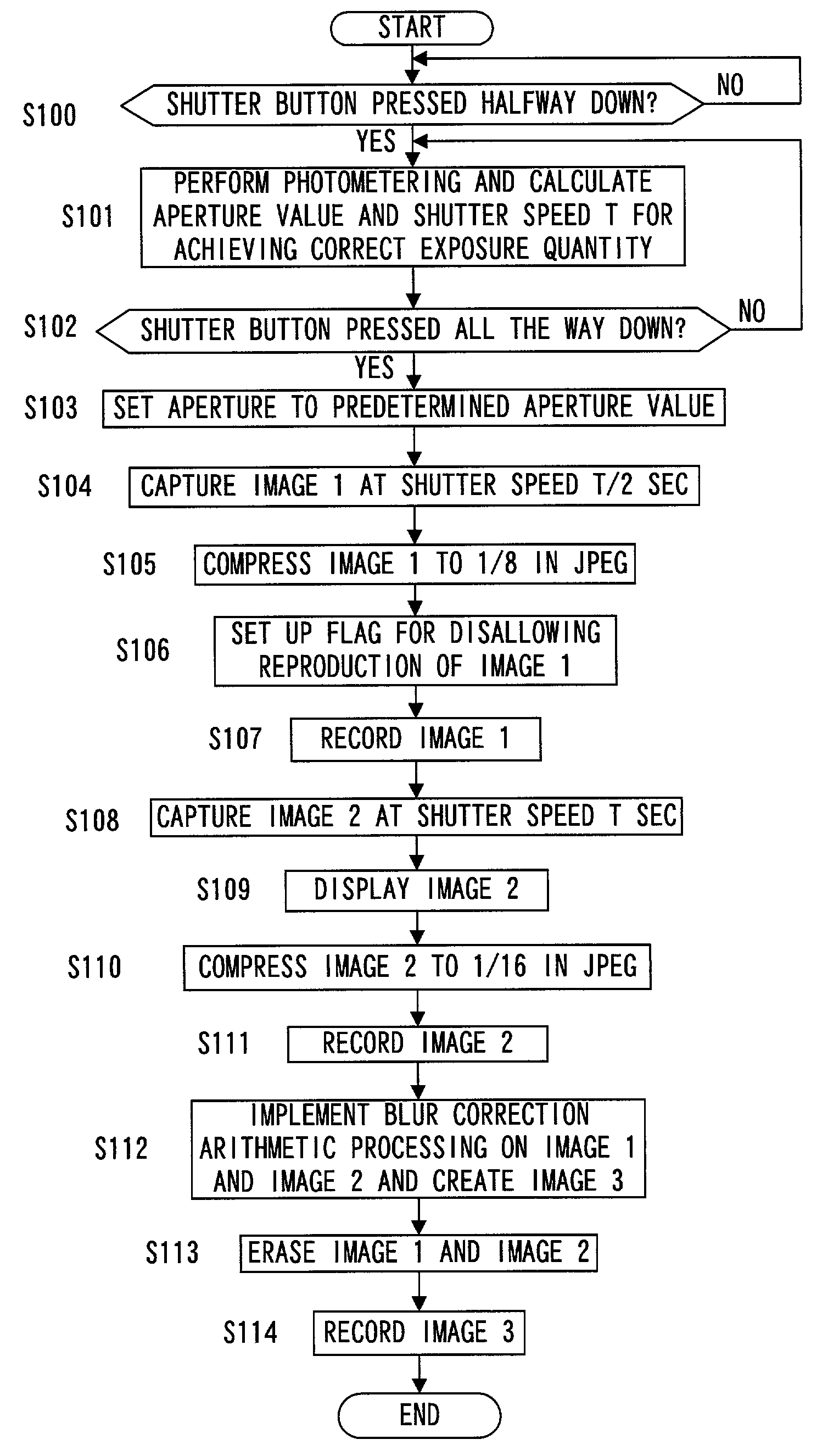
[0036]The digital camera achieved in the first embodiment of the present invention is explained in reference to the drawings.

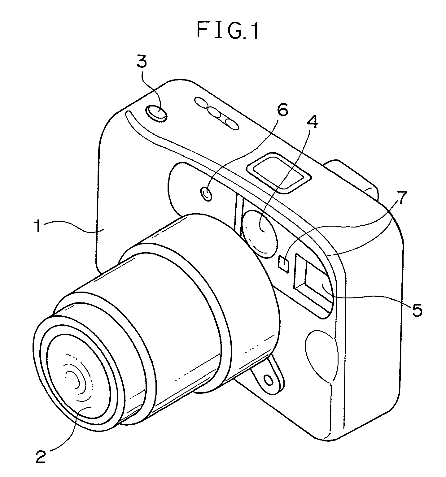
[0037]FIGS. 1 and 2 present perspectives of the external appearance of a digital camera 1 in the first embodiment of the present invention.

[0038]FIG. 1 is a perspective of the digital camera 1 viewed from the front. At the front surface of the digital camera 1, a photographic lens 2 that forms a subject image, a view finder 4 used when checking the subject photographing range, a light emitting unit (strobe) 5 that emits flash light to illuminate the subject during a photographing operation, a colorimetering element 6 that measures the color of the subject, a photometering element 7 that measures the brightness of the subject and the like are provided. At the top surface of the digital camera 1, a shutter release button 3 which is operated by the photographer when photographing the subject is provided.

[0039]FIG. 2 is a perspective of the digit...

second embodiment -

-Second Embodiment-

[0104]The basic structure of the digital camera achieved in the second embodiment is identical to the structure assumed in the first embodiment shown in FIGS. 1 and 2. In the second embodiment, blurred image correction processing is implemented by dividing an image into pixel data blocks corresponding to 16×16 pixels. The following is an explanation of the blurred image correction processing achieved in the second embodiment, given in reference to the flowchart presented in FIGS. 9 and 10. It is to be noted that the processing achieved in the second embodiment corresponds to that implemented in step S112 in the flowchart presented in FIG. 4 in reference to which the first embodiment has been explained earlier. The explanation below focuses on the difference from the first embodiment.

[0105]In step S300, the coordinate parameters x and y used to indicate the positions of the individual pixels of image 1 and the individual pixels of image 2 are initialized to 1.

[0106...

third embodiment -

-Third Embodiment-

[0119]An explanation has been given in reference to the first and second embodiments above by assuming that the image blur correction is implemented without emitting light at the strobe unit 5 when performing photographing operation. An explanation is now given in reference to the third embodiment on image blur correction control implemented during a flash photographing operation. FIG. 11 presents a flowchart of the procedure of image blur correction control processing implemented when light is emitted at the strobe unit 5. It is to be noted that the explanation given in reference to the third embodiment focuses on the difference from the first and second embodiments.

[0120]Since the processing performed in steps S400˜S403 is identical to the processing in steps S100˜S103 in FIG. 4, its explanation is omitted.

[0121]In step S404, the quantity Q of light to be emitted at the strobe unit 5 is calculated in correspondence to the photographing distance, the aperture valu...


PUM


Abstract

First image data and second image data are generated by capturing a subject image at a CCD. The first image data captured over a first exposure time manifest a relatively small extent of image blur. The second image data are captured over a second exposure time set longer than the first exposure time. A spatial frequency analysis is implemented on the first image data and the second image data to calculate the amplitude ratio and the phase difference of the high-frequency components in the two sets of image data. Based upon the amplitude ratio and the phase difference of the high-frequency components thus calculated, the spatial frequency component of the second image data is corrected to generate third image data in which any image blur has been corrected.

Description

INCORPORATION BY REFERENCE[0001]The disclosures of the following priority applications are herein incorporated by reference:[0002]Japanese Patent Application No. 2001-056096 filed Mar. 1, 2001[0003]Japanese Patent Application No. 2001-107429 filed Apr. 5, 2001BACKGROUND OF THE INVENTION[0004]1. Field of the Invention[0005]The present invention relates to a digital camera and an image processing system, and more specifically, it relates to a technology that may be adopted to generate an image by correcting an image blur.[0006]2. Description of Related Art[0007]The following methods have been proposed in the related art to be adopted in a camera to correct an image blur.[0008](1) A blur correction optical system is internally provided in the photographic optical system of the camera and a movement of the camera caused by an unsteady hand is detected with a movement detector. In correspondence to the detected camera movement, the blur correction optical system is moved during an image-...

Claims


Application Information

Patent Timeline
IPC IPC(8): H04N5/228H04N5/217H04N5/232H04N5/353H04N5/372
CPCH04N5/23248H04N5/23254H04N5/23261H04N5/2354H04N5/2327H04N5/23277H04N5/2353H04N5/23267H04N23/6815H04N23/684H04N23/6811H04N23/6845H04N23/683H04N23/68H04N23/73H04N23/74
Inventor EJIMA, SATOSHI
Owner NIKON CORP
Why Eureka
Try Eureka