
Framework system

a technology of framework and logic, applied in the field of framework system, can solve the problems of complicated scheduling, difficult to flexibly define the flow of complex business logic to accommodate diverse varieties of messages, etc., and achieve the effect of easy definition and chang

Active Publication Date: 2007-02-13
FUTURE SYST CONSULTING
View PDF20 Cites 8 Cited by
  • Summary
  • Abstract
  • Description
  • Claims
  • Application Information

AI Technical Summary

Benefits of technology

[0006]It is an object of the invention to provide a framework system in which flow of business logic is not programmed but is instead easily defined and changed.
[0013]In a preferred embodiment, moreover, one or more messaging services may be equipped with one or more nonvolatile message queues capable of protected storage of such secondary request message or messages. Such message queue or queues may be capable of preventing deletion of secondary request message or messages by continuing to store secondary request message or messages after such secondary request message or messages has or have been sent to framework service or services. In addition, such messaging service or services may be capable of resending secondary request message or messages stored in such nonvolatile message queue or queues to such a framework system as necessary.

Problems solved by technology

This makes it difficult to flexibly define flows of complex business logic to accommodate diverse varieties of messages.
This complicates scheduling, i.e., the decision of which server or servers to employ for execution of business logic.

Method used


Image

  • Framework system
  • Framework system
  • Framework system

Examples


Embodiment Construction

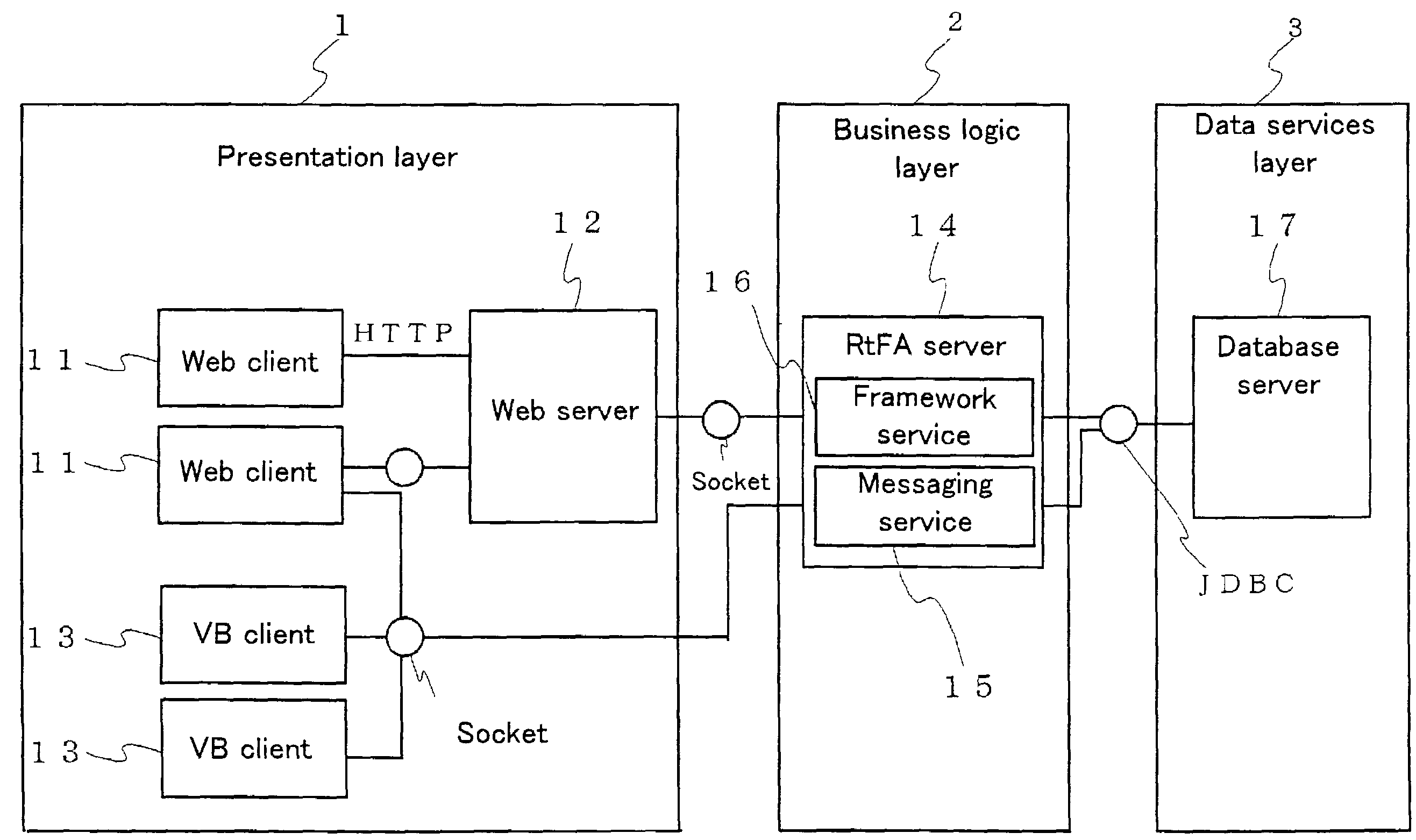
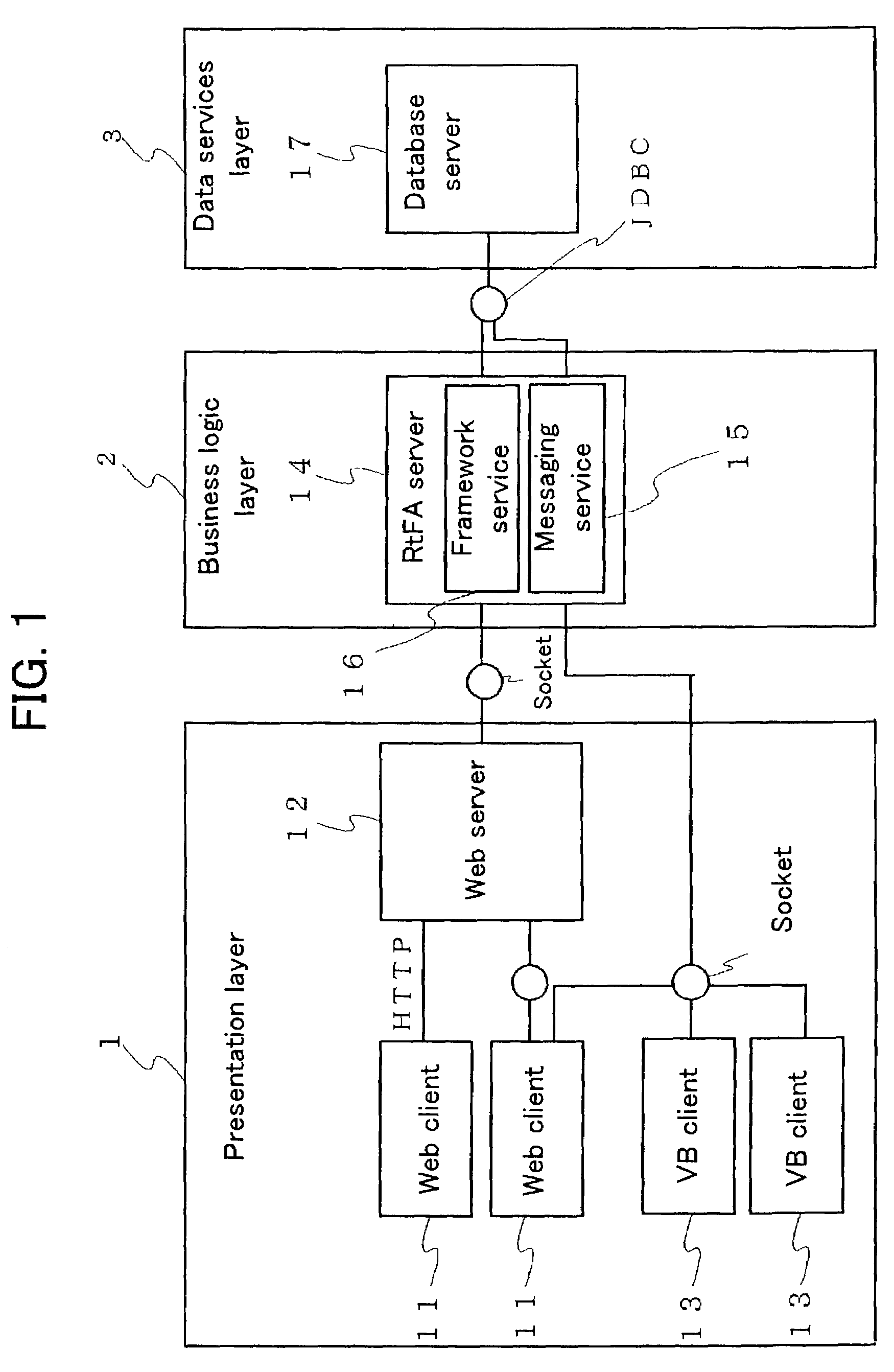
[0047]Below, an embodiment of the present invention is described with reference to the drawings. FIG. 1 shows the overall constitution of the present embodiment.

[0048]The present system is made up of presentation layer(s) 1, business logic layer(s) 2, and data services layer(s) 3.

[0049]Presentation layer(s) 1 comprises web (Word Wide Web) client(s) 11, web (Word Wide Web) server(s) 12, and VB (Visual Basic) client(s) 13.

[0050]Business logic layer(s) 2 is provided with RtFA server(s) 14, server computer system(s) on which framework architecture (referred to in the present specification as “RtFA” or “Real Time Framework Architecture”) in accordance with the principles of the present invention has been applied. RtFA server(s) 14 comprises server computer system(s) performing messaging service(s) (hereinafter simply “messaging service(s)”) 15 and server computer system(s) performing framework service(s) (hereinafter simply “framework service(s)”) 16. Messaging service(s) 15 and framewor...


PUM


Abstract

Disclosed is a framework system improved such that flow of complex business logic for processing a variety of messages may be easily defined and changed without need for programming. Messaging service(s) 15 may relay message(s) between client(s) 11, 13 and framework service(s) 16. Among request message(s) relayed from client(s) 11, 13 to framework service(s) 16 there may be message(s) comprising subject ID(s) associated with subject(s) of such message(s). Framework service(s) 16 may possess a plurality of sets of business logic 22 and flow definition file(s) 23. Flow definition file(s) 23 may comprise a plurality of definition sentences respectively corresponding to various subject IDs, and each such definition sentence may indicate schedule(s) for execution of business logic. Framework service(s) 16, upon receiving request message(s) from messaging service(s) 15, may select one or more sets of business logic for execution in accordance with execution schedule(s) corresponding to subject ID(s) of such message(s) indicated in definition file(s). Flow definition file(s) 23 can be rewritten at desired time or times notwithstanding the fact that framework service(s) 16 may be operational at such time(s). In the event that a plurality of sets of business logic are to be executed in linked fashion, framework service(s) 16 may execute subsequent business logic synchronously and / or asynchronously with respect to first business logic pursuant to execution schedule(s) indicated in definition sentence(s).

Description

FIELD OF ART[0001]The present invention pertains to a framework system capable of executing one or more selected sets of business logic responsive to one or more messages from one or more clients.BACKGROUND OF ART[0002]Such a framework system typically comprises one or more servers connected so as to be capable of communication with one or more clients. Such a framework system has conventionally been provided with the two basic functionalities represented by messaging service functionality and framework service functionality. A messaging service is a service that processes messages communicated between or among client or clients and server or servers, and / or between or among server or servers and server or servers. A framework service possesses one or more but ordinarily a plurality of sets of business logic (business operation process or processes), and performs one or more transactions by synchronously or a synchronously executing one or more selected sets of business logic respon...

Claims


Application Information

Patent Timeline
Patent Type & Authority Patents(United States)
IPC IPC(8): G06F15/16G06F9/46H04L12/58
CPCG06F9/546H04L51/18G06Q10/10H04L51/26H04L51/226
Inventor ISHIBASHI, KUNIHITOMAESHIMA, MITSURUOKUMURA, NARIHIROSAKASHITA, ISAOIGAKURA, YOKO
Owner FUTURE SYST CONSULTING
Learn More