
Address management in PNNI hierarchical networks

a hierarchical network and address management technology, applied in data switching networks, memory adressing/allocation/relocation, instruments, etc., can solve the problems of ptse no longer considered valid topology information, address being flushed from the network, etc., to reduce the length of time

Active Publication Date: 2007-02-13
IBM CORP
View PDF8 Cites 80 Cited by
  • Summary
  • Abstract
  • Description
  • Claims
  • Application Information

AI Technical Summary

Benefits of technology

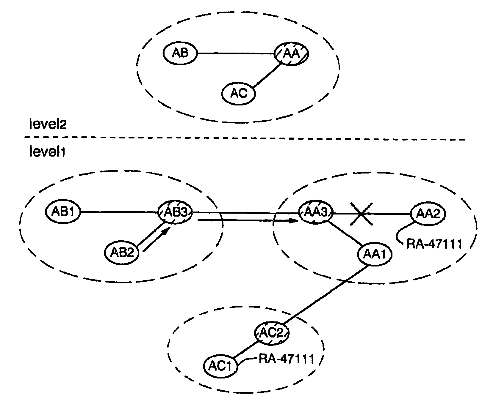
[0011]In accordance with the present invention, therefore, the peer group leader can check whether addresses, ie. reachable address prefixes, are actually accessible in the peer group. Changes in the accessibility, or connectivity, of addresses so identified can be notified to its neighboring nodes in the next hierarchy level. Since the peer group leader is able to check address connectivity rather than merely relying on the validity of the associated PTSE's until their lifetime expires, in embodiments of the present invention the problems discussed above can be alleviated or eliminated.
[0012]Various criteria may be applied to determine when address checking is performed and which addresses are checked. For example, systems may be envisaged where the peer group leader checks addresses represented by address data in one or both of its topology databases periodically. The interval between checks may be set at less than the PTSE lifetime or refresh period, the particular frequency being determined according to the requirements of a particular system. This would alleviate some of the problems discussed above by reducing the length of time that inaccessible addresses remain apparently available for access by the network.
[0014]As a particular example employed in preferred embodiments, when the peer group leader receives from its child peer group address data (eg by way of a PTSE) representing a new address, that is, an address which is not represented in said peer group topology data, the accessibility of that address within the peer group is checked. Then, only if the accessibility of the address is confirmed does the peer group leader supply address data representing that address to its neighbors in the next level of the hierarchy, for example by way of a PTSE, and update the peer group leader topology data with the new address data, eg. by storing the new PTSE. Thus, new addresses introduced within a peer group are advertised to the next level of the hierarchy only after checking that the address is accessible. This prevents irrelevant addresses, eg. from the old topology database of a mobile node moving to a new network access point, from being propagated in the network, thus preventing unnecessary network database changes and reducing transient topology database sizes, as well as avoiding the risk of routing via an invalid path which can otherwise result.

Problems solved by technology

It is this topology abstraction that reduces the resources required to define very large networks.
Thus, calls from outside a peer group to an address within the peer group may be instigated even though that address is in fact inaccessible, for example due to a link failure.
However, if a PTSE's lifetime expires without the PTSE being refreshed, the PTSE is no longer considered valid topology information and is removed, or “flushed” from the topology database.
Thus, if an address becomes inaccessible due to loss of connectivity within the peer group, expiry of the associated PTSE will eventually result in the address being flushed from the network (assuming connectivity is not restored in the meantime).
Additional problems may arise with the existing scheme apart from that of unnecessary calls being placed to inaccessible addresses.
This can result in irrelevant addresses being advertised in the network, and presents the risk of routing via an invalid path.
As a further example, a serious problem can arise with the existing scheme in the case where a backup service is advertising the same reachable address as a primary service, for example a LECS (LAN Emulation Client Server).

Method used


Image

  • Address management in PNNI hierarchical networks
  • Address management in PNNI hierarchical networks
  • Address management in PNNI hierarchical networks

Examples


Embodiment Construction

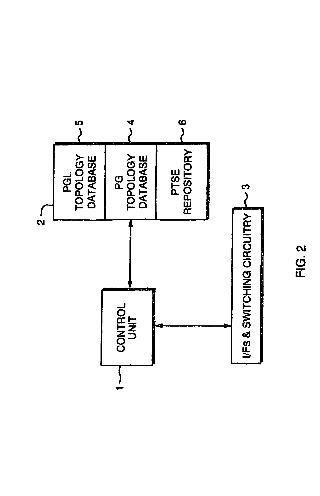
[0031]FIG. 2 is a schematic block diagram of an embodiment of a network device showing the main elements involved in implementing address management methods embodying the invention. As shown in the figure, the device, such as an ATM switch, comprises a control unit 1, a memory 2, and circuitry 3 which represents the interfaces (I / Fs) and switching fabric which connect the device with its links to neighboring nodes and via which the device communicates with the rest of the network. The control unit 1 controls operation of the device generally, and includes address management apparatus in the form of control logic (not shown separately) which controls the address management functions to be described below. The control logic may be implemented in hardware or software (program code), or a combination thereof, and suitable implementations will be apparent to those skilled in the art from the following description. In particular, the control unit 1 may be implemented by a suitably program...


PUM


Abstract

Address management methods and apparatus are provided for a node serving as peer group leader for a peer group of nodes in one level of the hierarchy of a PNNI hierarchical network, whereby the peer group leader represents the peer group to one or more neighboring nodes in the next level up of the hierarchy. The peer group leader has a memory (2) for storing peer group topology data (4), comprising address data which is supplied to the peer group leader from nodes in the peer group and represents addresses for access by the network, and peer group leader topology data (5), comprising address data which is supplied to said neighboring nodes by the peer group leader and represents addresses accessible via the peer group. The address management method comprises: checking whether addresses represented by said address data are accessible via the peer group; notifying said neighboring nodes of changes in the accessibility of addresses so identified; and updating said peer group leader topology data (5) in accordance with said changes.

Description

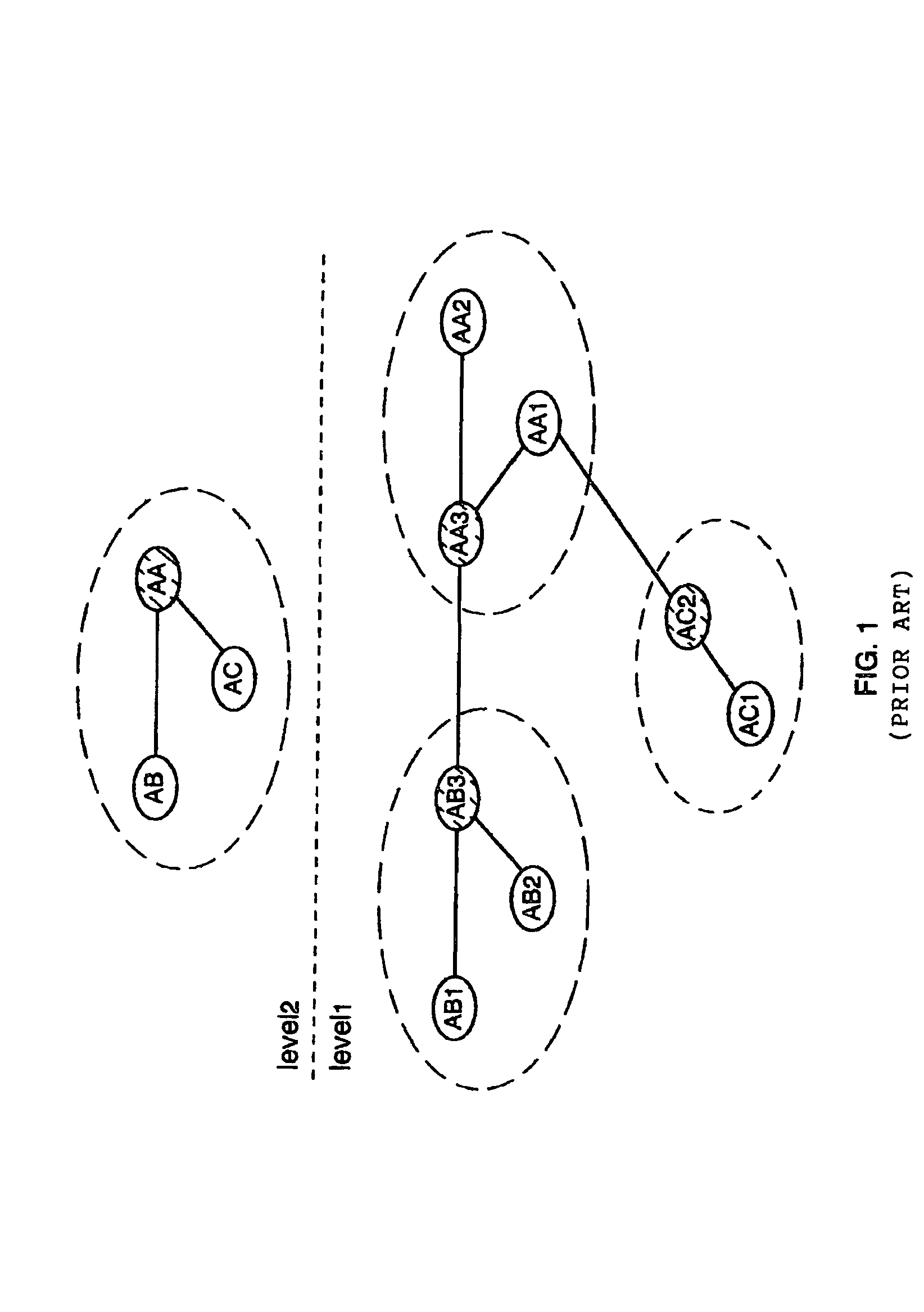
FIELD OF THE INVENTION[0001]This invention relates generally to address management in PNNI hierarchical networks, and more particularly to the management of addresses in accordance with their accessibility in such networks.BACKGROUND OF THE INVENTION[0002]PNNI (Private Network-to-Network Interface) is a hierarchical, dynamic link-state routing protocol defined by the ATM (Asynchronous Transfer Mode) Forum for use in ATM networks. The hierarchy extension and the use of a single routing protocol at all levels of the hierarchy allow the support for large-scale ATM networks. A key feature of the protocol is the ability to cluster network nodes into manageable groups called “peer groups”. One node in each peer group serves as the “peer group leader” and represents that peer group as a single logical node (“logical group node” or LGN) in the next level up of the hierarchy. This concept is illustrated schematically in FIG. 1 of the accompanying drawings which shows a simple two-level hiera...

Claims


Application Information

Patent Timeline
IPC IPC(8): G06F15/16G06F9/44G06F12/08G06F13/00H04L45/02H04L49/111H04Q11/04
CPCH04L61/6004H04L61/35H04Q11/0478H04L29/12009H04L29/12254H04L29/12783H04L29/12801H04L45/02H04L45/04H04L49/3081H04L61/2038H04L2012/5627H04L2012/5685H04L41/0893H04L41/12H04L2012/5621H04L61/00H04L61/5038H04L2101/604
Inventor DYKEMAN, DOUGLASOSBOURNE, MICHAELSCOTTON, PAOLOSTOKES, OLENBASSO, CLAUDEAUBRY, MARIANNEKHAC, MINH-TRI DO
Owner IBM CORP
Learn More