
Refrigeration power plant

a technology for refrigerating power plants and power plants, which is applied in the direction of machines/engines, light and heating equipment, machine operation modes, etc., to achieve the effect of low maintenance requirements and little electrical energy

Inactive Publication Date: 2007-02-20
SIEMENS AG
View PDF18 Cites 33 Cited by
  • Summary
  • Abstract
  • Description
  • Claims
  • Application Information

AI Technical Summary

Benefits of technology

This solution enables economical and flexible generation of refrigeration, reducing energy costs and maintenance needs, while utilizing existing power station infrastructure to provide combined heat, power, and refrigeration, enhancing the efficiency and scalability of power stations.

Problems solved by technology

Said type of decentralized provisioning with refrigeration is very demanding in terms of cost and energy because either block-type thermal power stations have to be specially set up for the purpose of supplying consumers who have substantial refrigeration requirements or, in the case of refrigeration provisioning carried out directly on domestic premises, a large amount of electrical energy has to be expended in order to generate the required amount of refrigeration.

Method used


Image

  • Refrigeration power plant
  • Refrigeration power plant
  • Refrigeration power plant

Examples


Embodiment Construction

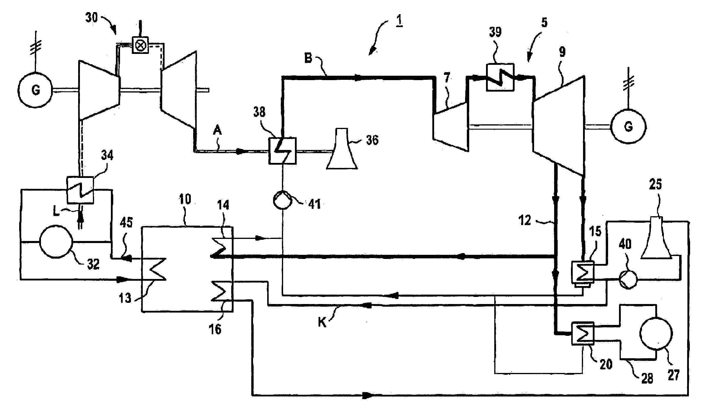
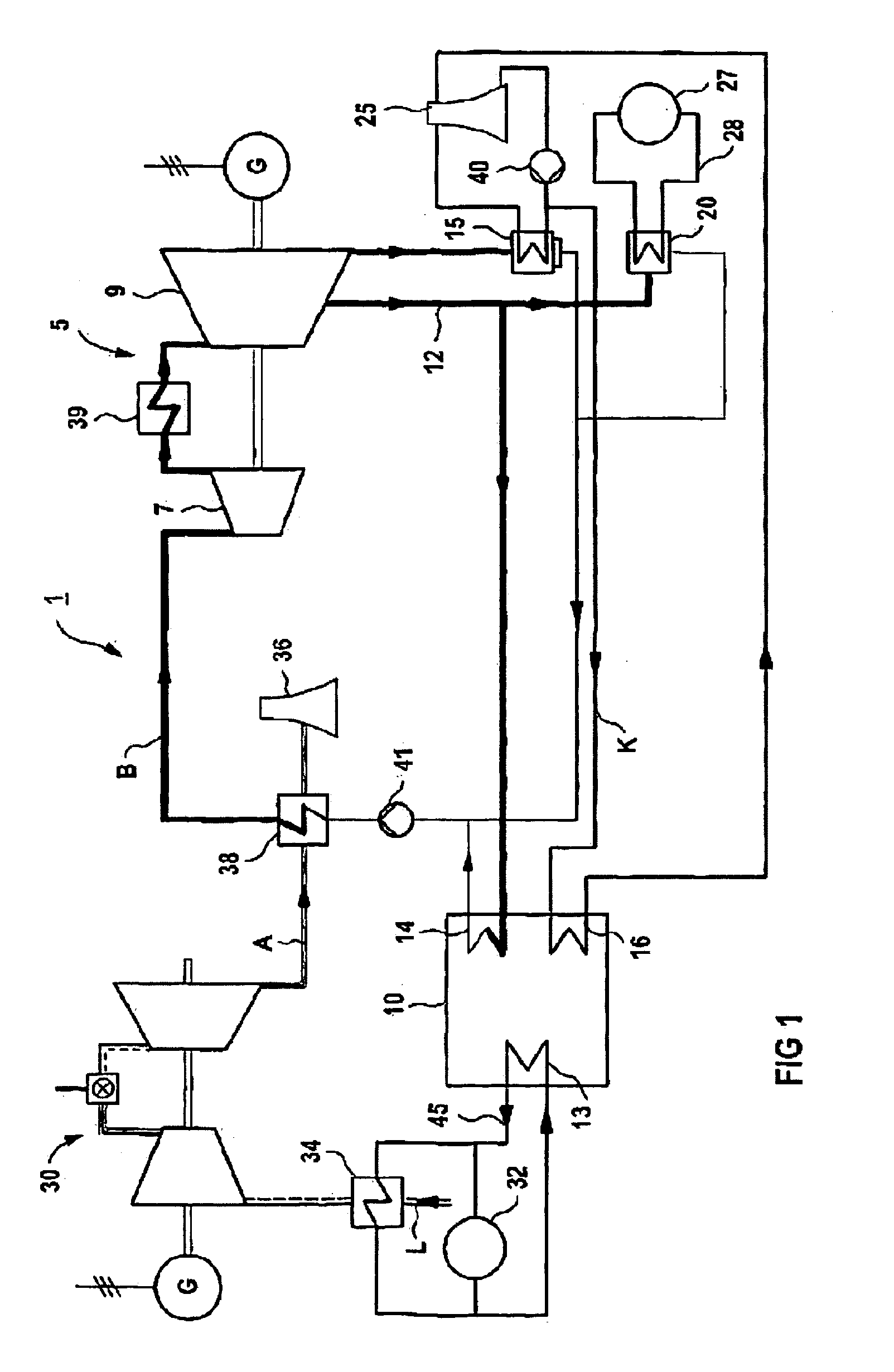
[0042]The figure is a schematic of a power station 1 according to the invention which is embodied as a gas-and-steam system and includes a steam turbine 5 and a gas turbine 30.

[0043]The operating steam B of the steam turbine 5 is made available by means of the waste heat A of the gas turbine 30.

[0044]The steam turbine 5 includes a high-pressure section 7 and a low-pressure section 9.

[0045]An absorption-type refrigeration machine 10 is operated by means of extracted steam 12 used as a heat source. Said extracted steam 12 is routed to an expeller 14 of the absorption-type refrigeration machine 10, said expeller sustaining the absorption process of the absorption-type refrigeration machine 10. The output of the expeller 14 is linked via a pump 41 to a heating surface 38 which is heated by the waste heat A of the gas turbine 30 in order to generate the operating steam B necessary for operating the steam turbine 5. The exhaust gas of the gas turbine 30 is routed after heat exchange with ...


PUM


Abstract

The invention relates to a power station comprising at least one steam turbine and / or gas turbine which is connected to at least one absorption type refrigeration machine in order to produce refrigeration, whereby the absorption type refrigeration machine is operated by means of steam which is taken from the steam turbine, or by means of waste heat produced by the gas turbine.

Description

CROSS REFERENCE TO RELATED APPLICATION[0001]This application is the US National Stage of International Application No. PCT / DE03 / 00857, filed Mar. 17, 2003 and claims the benefit thereof. The International Application claims the benefits of German Patent application No. 10214183.5 DE filed Mar. 28, 2002, both of the applications are incorporated by reference herein in their entirety.FIELD OF THE INVENTION[0002]The invention relates to a power station having at least one steam turbine and / or at least one gas turbine.BACKGROUND OF THE INVENTION[0003]One of today's major objectives to be met by technological means is to ensure the economical handling of available energy resources in generating and consuming power.[0004]Power plants which are sizeable in terms of their installed generating capacity and which supply a large number of consumers and extensive geographical areas with electrical energy and district heat on a centralized basis are frequently employed to generate electrical ene...

Claims


Application Information

Patent Timeline
Patent Type & Authority Patents(United States)
IPC IPC(8): F25B1/00F01K17/04F01K17/00F01K17/02F01K23/10F02C6/18F02C7/143F25B27/02
CPCF01K17/005F02C6/18F25B27/02Y02E20/16F25B2333/007Y02E20/14Y02A30/274
Inventor STUHLMUELLER, FRANZ
Owner SIEMENS AG
Learn More