
Versatile bandsaw blade

a bandsaw blade and bandsaw blade technology, applied in the field of bandsaw blades, can solve the problems of insufficient tooth pitch, blades seldom changed, insufficient tooth strength and beam strength of the operator of the saw machine, etc., and achieve the effect of sufficient tooth strength and beam strength

Inactive Publication Date: 2007-02-20
KAPMAN
View PDF11 Cites 24 Cited by
  • Summary
  • Abstract
  • Description
  • Claims
  • Application Information

AI Technical Summary

Benefits of technology

[0015]The advantages of a bandsaw blade according to the present invention are that both the tooth strength and the strength of the beam are sufficiently high, that the gullets will be dimensioned to the required chip capacity and that unwanted scrap due to mispitching while setting the teeth is reduced.

Problems solved by technology

It is not unusual that the operator of the saw machine is inexperienced and not properly trained in the use of the machine.
Blades are seldom changed when cutting a new work piece, which is why the choice of bandsaw blade type and tooth pitch is not always done in the optimal way.
The upkeep of the machine is often neglected, which is why cuts are frequently made without properly using the chip brush.
The consequence of these circumstances is that the saw blades are frequently prematurely destroyed.
They are destroyed because the teeth are broken.
The teeth break either because too coarse of a tooth pitch is used when cutting small work pieces such as thin walled tubes or profiles, or because too fine of a pitch is used when cutting large work pieces or when too high of a feed rate or too low of a band speed is used.
When too coarse of a pitch is used, the teeth break because the teeth are overloaded.
When too fine of a pitch is used, or when too high of a feed rate or too low of a band speed is used, or the chip brush is not properly used, the gullets are completely filled and excessive pressure is built up in the gullet, leading to tooth breakage.
In deep gullets with small radii, the risk of swarf becoming locked in the gullet is increased.
If the wrong tooth is left unset, the setting hammers will hit the other teeth in the group in such a way that the teeth or the edges are deformed in an unwanted way.
This leads to high amount of scrapped material in the production of such bandsaw blades.
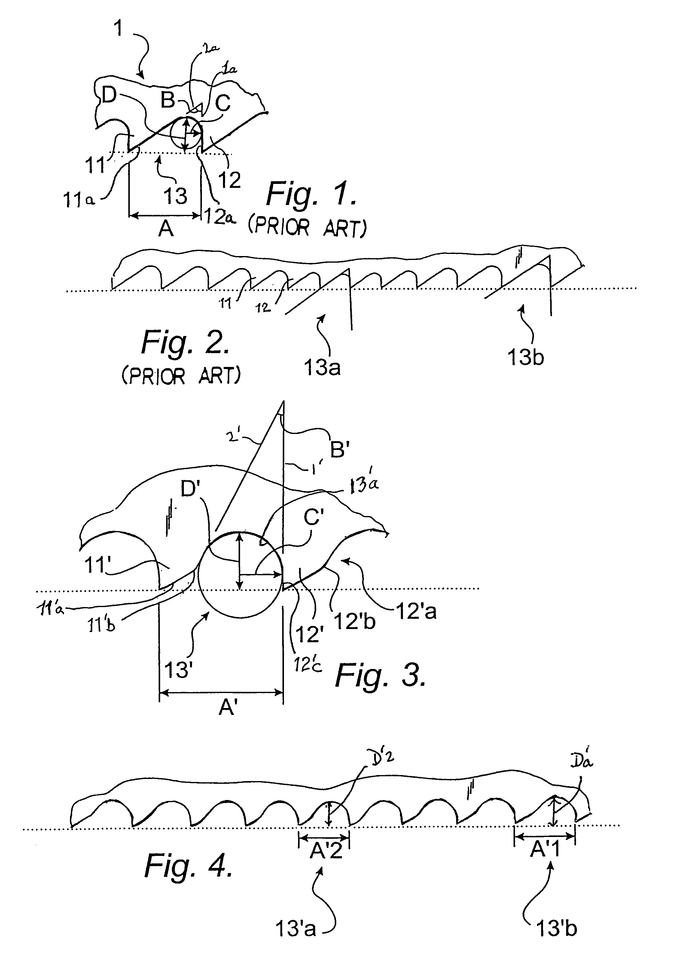
The chip holding capacity of the gullets in such a design is limited by the cross sectional area of the smallest gullet in the group.
The other, bigger gullets in the group are unnecessarily big because all their dimensions are proportional to the tooth distance in relation to the smallest gullet.
This will result in gullet depths that are deeper than necessary, leading to reduced beam strength of the blade.

Method used


Image

  • Versatile bandsaw blade
  • Versatile bandsaw blade
  • Versatile bandsaw blade

Examples


Embodiment Construction

[0021]FIG. 1 shows a conventional bandsaw blade 1 with leading and trailing teeth 11,12 separated by a gullet 13. Parameters pertinent to the present invention are the tooth distance A, the clearance angle B, the radius C of the gullet 13, and the depth D of the gullet 13. The expression “leading tooth” as used herein refers to any tooth which leads another, trailing tooth. A bottom of each gullet is radiused with a radius C. A clearance angle B is defined between successive teeth, each clearance angle B formed between a first line 1 which is tangent to the radiused bottom at a point where the radiused bottom joins the front 12c of the trailing tooth 12, and a second line 2 which is tangent to the radiused bottom of the gullet at a point where the radiused bottom joins to the back 11a of the leading tooth 11.

[0022]FIG. 2 shows a known bandsaw blade where the teeth are divided into groups, each group repeating the same variation in tooth distance. The figure shows that the smallest g...


PUM

PropertyMeasurementUnit
Angleaaaaaaaaaa
Angleaaaaaaaaaa
Ratioaaaaaaaaaa

Abstract

A bandsaw blade includes a blade beam carrying a plurality of cutting teeth separated by gullets. A clearance angle of the teeth is smaller than 35°, and the back of a leading tooth has a convex transition to a gullet. The radius of the gullet is larger than ½ of the depth of the gullet.

Description

FIELD OF INVENTION[0001]The present invention relates to a versatile bandsaw blade comprising a blade beam carrying a plurality of cutting teeth.BACKGROUND OF THE INVENTION[0002]Bandsawing is the preferred method for cutting long pieces of metal into predetermined lengths as a preparation for other operations such as welding, turning and milling.[0003]When using bandsaw blades in maintenance and other smaller workshops it is common to cut a wide variety of work piece materials and sizes. It is not unusual that the operator of the saw machine is inexperienced and not properly trained in the use of the machine. Blades are seldom changed when cutting a new work piece, which is why the choice of bandsaw blade type and tooth pitch is not always done in the optimal way. The upkeep of the machine is often neglected, which is why cuts are frequently made without properly using the chip brush.[0004]The consequence of these circumstances is that the saw blades are frequently prematurely destr...

Claims


Application Information

Patent Timeline
IPC IPC(8): B23D57/00B27B33/02B23D61/12
CPCB23D61/121Y10T83/9319Y10T83/9346Y10T83/935
Inventor HELLBERGH, HAKAN
Owner KAPMAN
Learn More