
Continuous casting roll

a continuous casting and roll technology, applied in the field of continuous casting roll, can solve the problems of loading stress, crack formation in response to acting fatigue stress, etc., and achieve the effect of reducing effective stress and shrinking stress

Inactive Publication Date: 2007-02-20
KME GERMANY GMBH & CO KG
View PDF4 Cites 0 Cited by
  • Summary
  • Abstract
  • Description
  • Claims
  • Application Information

AI Technical Summary

Benefits of technology

"The present invention relates to a continuous casting roll with a relaxation zone between the core and the jacket, which helps to reduce stress and prevent material fatigue and crack formation. The relaxation zone is formed by a profiling of the outer diameter of the core and / or the inner diameter of the jacket. The invention also includes a force-locking connection between the core and the jacket, which ensures reliable connection, while reducing the shrinking stresses in the highly stressed ranges. The technical effects of the invention are improved service life and running properties of the continuous casting roll, as well as reduced effective stresses and increased fatigue resistance."

Problems solved by technology

As a result, in the edge zones of the continuous casting roll, load stresses may arise which overlap with the acting stresses from the shrinking procedure.
These stresses, under load, may lead to the formation of cracks in response to the acting fatigue stress.

Method used


Image

  • Continuous casting roll
  • Continuous casting roll

Examples


Embodiment Construction

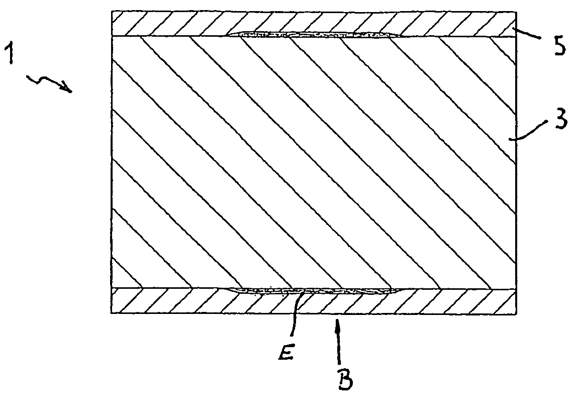
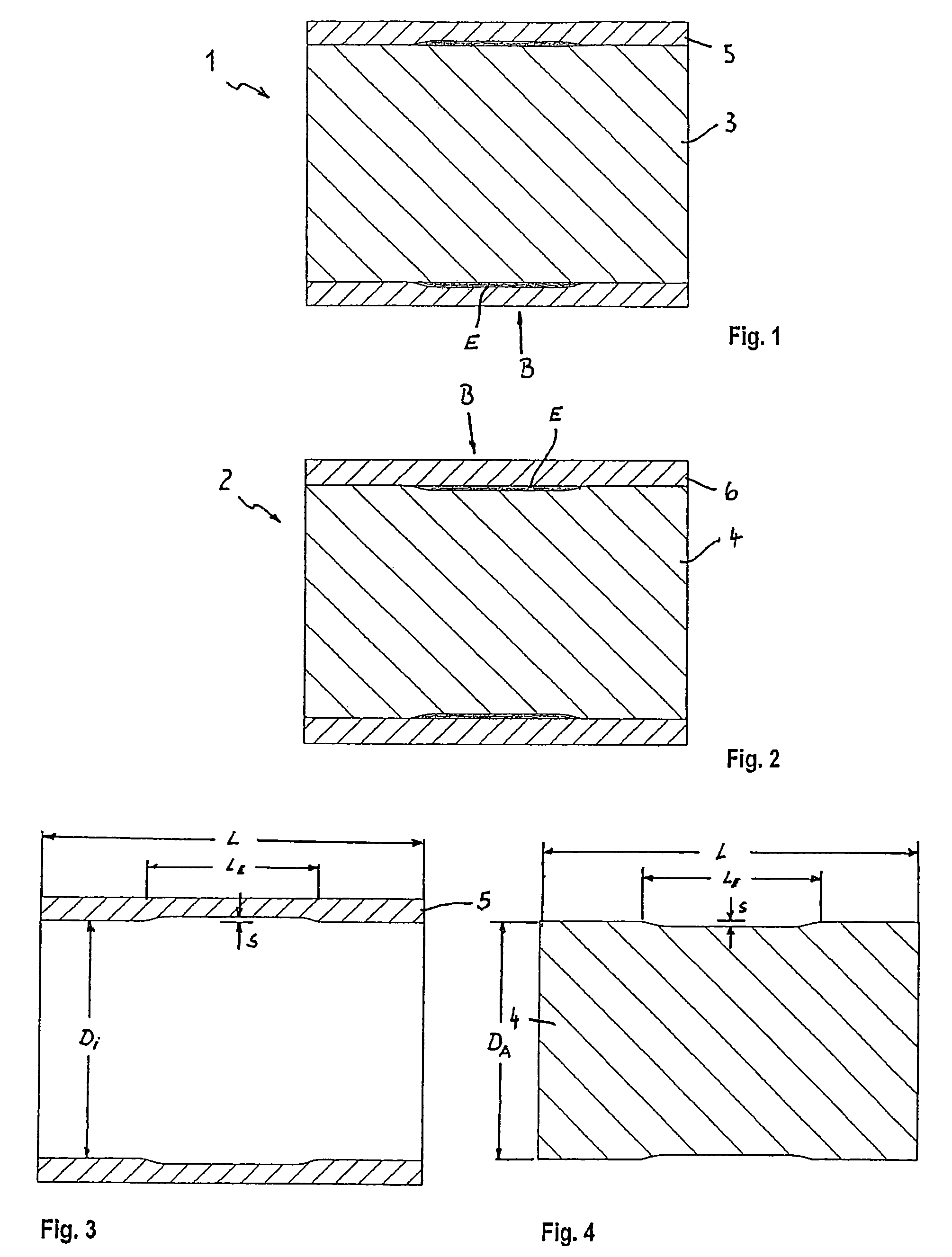
[0019]FIGS. 1 and 2 each show a continuous casting roll 1 or 2 for a continuous cast-rolling plant for continuous casting of metal strip. Each of continuous casting rolls 1, 2 has a cylindrical core 3, 4 made of steel, and a jacket 5, 6, made of a copper alloy, shrunk onto it.

[0020]For clarity, additional components, such as the shaft, bearings and other add-on parts, or cooling channels, are not shown in the drawings.

[0021]As indicated above, jacket 5 or 6 and core 3 or 4 are connected to one another respectively by a shrinking technique. Because of the shrinking procedure, the jacket 5, 6 experiences tensile stress. These stresses superimpose themselves on the operating load stresses to form the so-called effective stress. This maximum stress is created in the middle region, labeled B, of a continuous casting roll 1 or 2. These regions B tend to be favored when it comes to crack formation under load, in response to fatigue stress.

[0022]In order to reduce the shrinking stresses tha...


PUM

PropertyMeasurementUnit
diameteraaaaaaaaaa
heat conductivityaaaaaaaaaa
radial thicknessaaaaaaaaaa

Abstract

A continuous casting roll for the continuous casting of metal strip. The continuous casting roll has an essentially cylindrical core and a jacket, for example, made of a copper alloy, that is shrunk onto it. A relaxation zone is provided between the core and jacket. The relaxation zone, for example, having a radial extension of 1 mm, may be formed by a regional increase in the inside diameter of the jacket, and may be situated in the middle longitudinal range of the jacket.

Description

RELATED APPLICATIONS[0001]The present application claims priority to German Patent Application Serial No. 103 37 174.5, filed Aug. 13, 2003, the entire disclosure of which is incorporated herein by reference.FIELD OF THE INVENTION[0002]The present invention relates to a continuous casting roll for a cast-rolling plant for the continuous casting of metal strip.BACKGROUND INFORMATION[0003]In cast-rolling, liquid steel or other, nonferrous metals are cast between two continuous casting, counter-rotating rolls that are horizontally or vertically situated one over the other and sealed on their sides. In this operation, the strip solidifies between the two continuous casting rolls and is continuously advanced in the process.[0004]Continuous casting rolls of the current design type have a cylindrical core, usually made of steel, and a jacket connected to it. In the cast-rolling of steel, substances having high heat conductivity, such as copper or copper alloys are usually employed as the m...

Claims


Application Information

Patent Timeline
Patent Type & Authority Patents(United States)
IPC IPC(8): B22D11/12B22D11/06
CPCB22D11/0651
Inventor KOLBECK, DIETMARWOBKER, HANS-GUNTERHUGENSCHUTT, GERHARD
Owner KME GERMANY GMBH & CO KG
Learn More