System and method for directional drilling utilizing clutch assembly

a clutch assembly and directional drilling technology, applied in the direction of directional drilling, drilling pipes, drilling rods, etc., can solve the problems of wellbore deviation and difficulty of directional drilling, and achieve the effect of reducing or eliminating static friction

Inactive Publication Date: 2007-02-20
EFFECTIVE EXPLORATION
View PDF67 Cites 77 Cited by
  • Summary
  • Abstract
  • Description
  • Claims
  • Application Information

AI Technical Summary

Benefits of technology

[0007]Embodiments of the invention may provide numerous technical advantages. Some embodiments may benefit from some, none, or all of these advantages. For example, according to certain embodiments, a clutch assembly associated with the drill string allows rotation of a majority of the drill sting while preventing rotation of the portion of the drill string that contains the drill motor and bit. This substantially reduces or eliminates any static friction between the majority of the rotated drill string and wall of the wellbore, thereby allowing directional drilling with a bent motor to be performed in an efficient manner. That portion of the drill string between the clutch assembly and the drill motor and bit includes enough weight to resist the reactive torque of drill motor, thereby providing stability for maintaining orientation of the bent motor assembly. This lower section slides along the path of the wellbore while the rotating upper section, free from static friction, effectively transfers the necessary force to advance the sliding section ahead. In particular embodiments, the clutch assembly may be actuated by altering the fluid flow down the drill string.

Problems solved by technology

This “directional drilling” may be difficult due to static friction between the non-rotating drill string and wall of the wellbore, especially for long drill strings.
Additionally, rotary steerable systems may be used, in which the entire drill string continues to rotate while adjustable near-bit stabilizers force the drill pipe to become eccentric within the wellbore, thus causing wellbore deviation to take place.

Method used


Image

  • System and method for directional drilling utilizing clutch assembly
  • System and method for directional drilling utilizing clutch assembly
  • System and method for directional drilling utilizing clutch assembly

Examples


Embodiment Construction

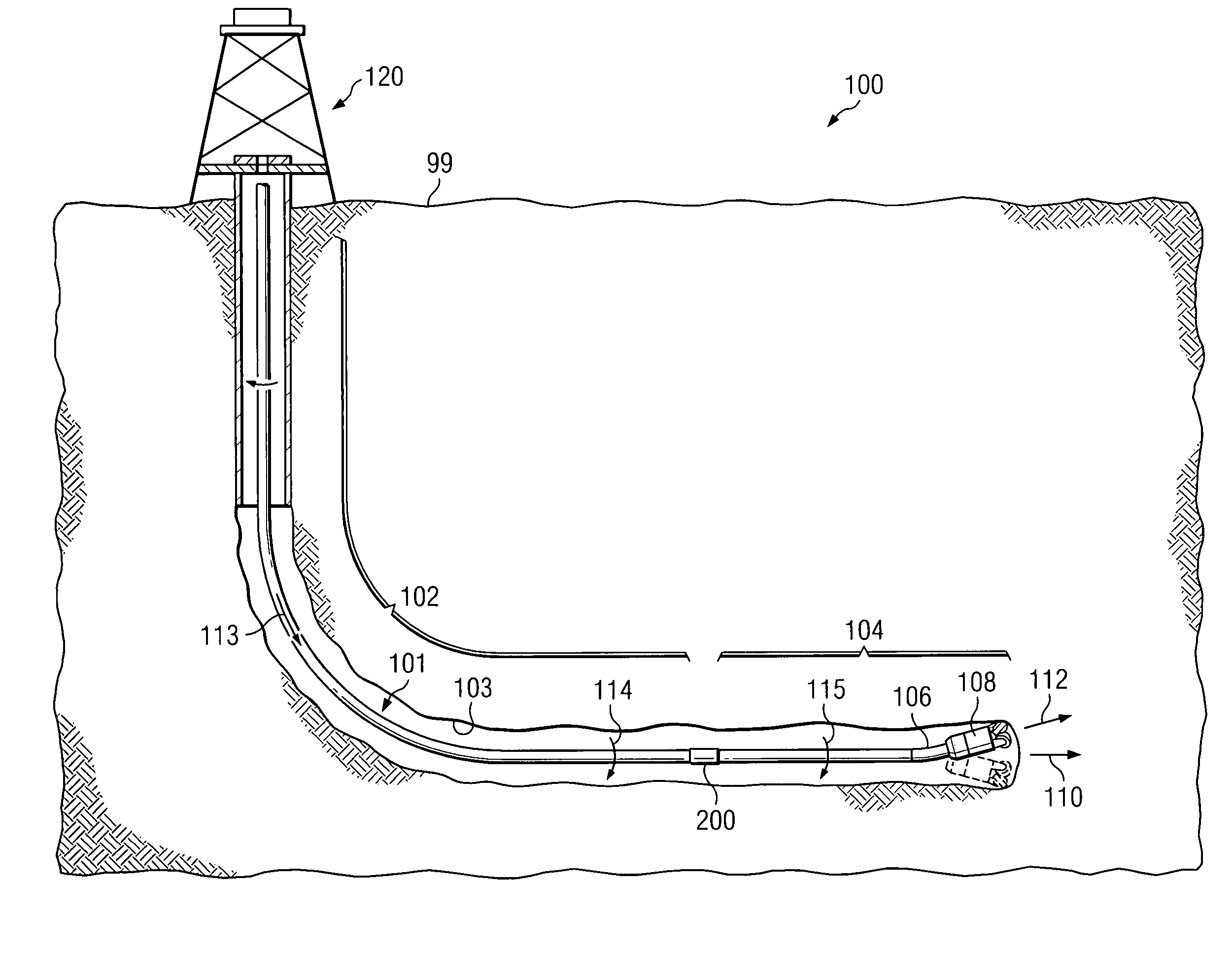
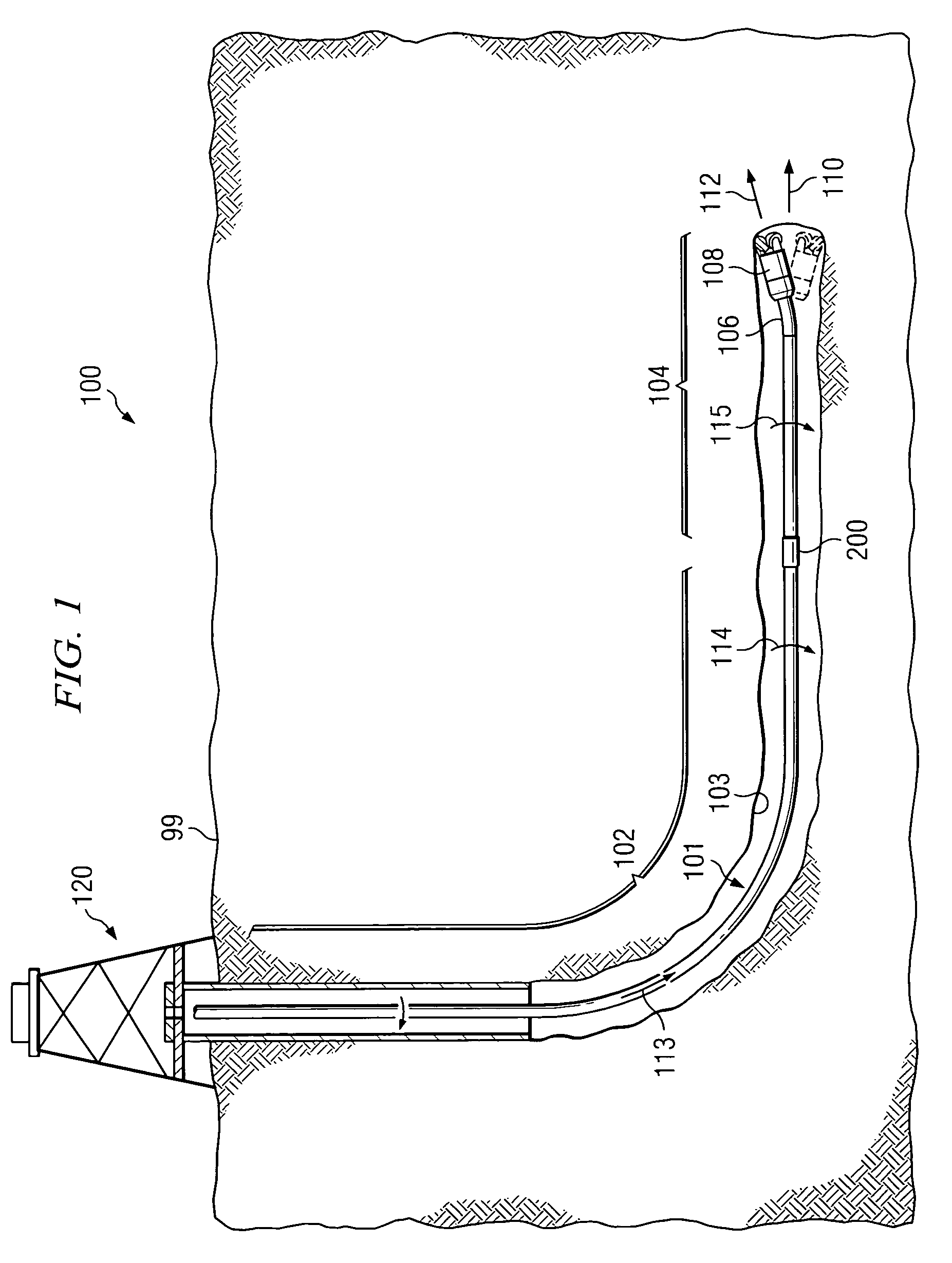
[0013]FIG. 1 is a schematic diagram of a system 100 for directional drilling within a wellbore 103 in accordance with one embodiment of the present invention. In the illustrated embodiment, system 100 is being utilized for directional drilling to alter the direction of wellbore 103 from a first direction 110 to a second direction 112. Both first direction 110 and second direction 112 may be any suitable direction below a ground surface 99. System 100 may be used to drill a wellbore having any type of change in direction, including without limitation, an articulated wellbore or any type of wellbore (including an articulated or slanted wellbore) from which one or more lateral wellbores are drilled.

[0014]In the illustrated embodiment, system 100 includes a drill string 101 having an upper portion 102, a lower portion 104, a bent motor 106, a drill bit 108, and a clutch assembly 200 disposed between upper portion 102 and lower portion 104.

[0015]According to the teachings of particular e...


PUM


Abstract

According to one embodiment of the invention, a system for directional drilling within a wellbore includes a drill string having an upper portion, a lower portion, a bent motor coupled to the lower portion, and a drill bit coupled to bent motor, and a clutch assembly disposed between the upper and lower portions. The clutch assembly is operable to disengage the upper and lower portions of the drill string and allow the upper portion to rotate while the lower portion does not rotate.

Description

TECHNICAL FIELD OF THE INVENTION[0001]This invention relates generally to the field of drilling systems and, more particularly, to a system and method for directional drilling utilizing a clutch assembly.BACKGROUND OF THE INVENTION[0002]Drilling wellbores in the earth, such as wellbores used for the production of oil and gas, is a well established art. One type of drilling system is rotary drilling, which uses a drill bit at the end of a drill string to drill into the earth. At the surface, a drilling rig controls the position and rotation of the drill string below the surface. Underneath the surface, the drill bit is attached to the drill string that transports drilling fluid to the drill bit. The drilling fluid lubricates and cools the drill bit and also functions to remove cuttings and debris from the wellbore as it is being drilled.[0003]While simple rotary drilling has been employed for many years, directional drilling is becoming a more common drilling practice. Directional dr...

Claims


Application Information

Patent Timeline
Patent Type & Authority Patents(United States)
IPC IPC(8): E21B7/04E21B7/06E21B17/04
CPCE21B17/04E21B7/067
Inventor ZUPANICK, JOSEPH A.
Owner EFFECTIVE EXPLORATION
Why Eureka
Try Eureka