Overhead conveyer with high friction drive tube

a technology of drive shaft and drive shaft, which is applied in the direction of conveyor parts, mechanical conveyors, railway components, etc., can solve the problems of increasing the friction between the drive shaft and the drive shaft, adding expensive processing to the manufacturing, and not enough, so as to improve the traction and production time and cost. , the effect of improving the traction

Inactive Publication Date: 2007-02-20
TABLER CHARLES P
View PDF15 Cites 33 Cited by
  • Summary
  • Abstract
  • Description
  • Claims
  • Application Information

AI Technical Summary

Benefits of technology

[0010]One or more driven wheels are rotatably mounted on the carriage for rotation about one or more drive axes, each of which is non-parallel and non-perpendicular to the shaft axis. Each driven wheel engages a peripheral portion of the drive shaft with sufficient traction so as to form a helical loci of engagement about the periphery of the drive shaft during rotation of the drive shaft about the shaft axis to power the carriage along the conveying path in a direction of the conveying path dependent upon a direction of rotation of the drive shaft. Traction is improved by ridges of the drive shaft inter-engaging with the driven wheel, particularly with an elastic and / or rigid ridged driven wheel. There are advantages of production time and cost when the drive shaft ridges are extruded parallel to the shaft axis during the manufacturing of the shaft.

Problems solved by technology

This well known slippage problem of the rotatable drive shaft type of overhead conveyor has been partially solved by sand-blasting and then anodizing aluminum drive shafts, which adds expensive processing to the manufacturing.
Though this is an improvement for some applications, in many cases, it is not enough.
In addition to ascents and to a lesser extent, descents, the problem arises in other circumstances, for example: when a carriage with spaced apart trolleys for a single load (two trolleys being used to carry a greater load than can be carried with a single trolley) passes through a switch.
Therefore, there is a need to increase drive friction between the drive shaft and driven rollers of the rotatable drive shaft type of overhead conveyor systems at least at selected locations of a system where a slippage problem is most likely to occur.

Method used


Image

  • Overhead conveyer with high friction drive tube
  • Overhead conveyer with high friction drive tube
  • Overhead conveyer with high friction drive tube

Examples


Embodiment Construction

[0020]Referring now to the drawings, wherein like reference numerals designate identical or corresponding parts throughout the several views.

[0021]The overhead conveying system 10 of an exemplary embodiment of the invention may be of any of the types shown in the above-mentioned patents.

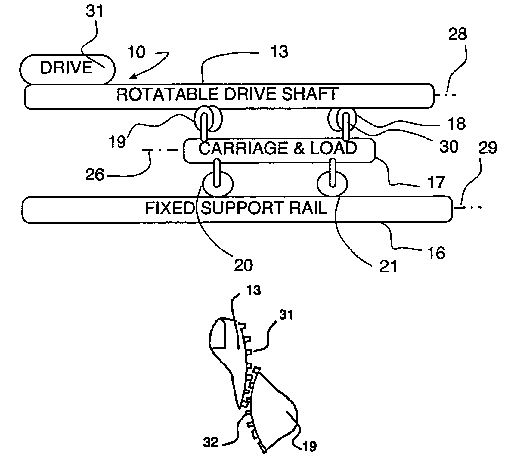
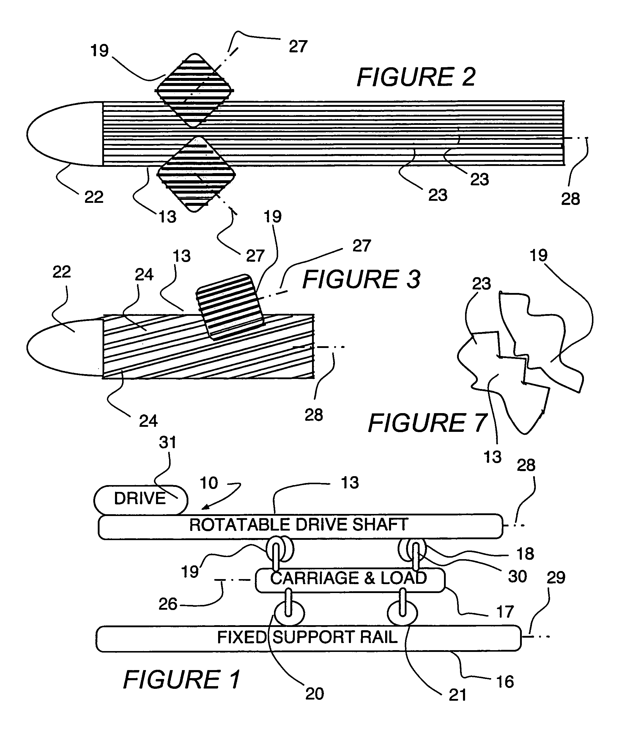
[0022]By way of a specific best mode example, the embodiment shown in the drawing is of the type wherein a plurality of carriages and loads 17 (one being shown) travel along a conveying direction 26 as they are supported on a fixed support rail 16 by a plurality of freely rotating support wheels 20, 21. The fixed support rail 16 has its longitudinal extent or axis 29 extending parallel to the conveying direction 26.

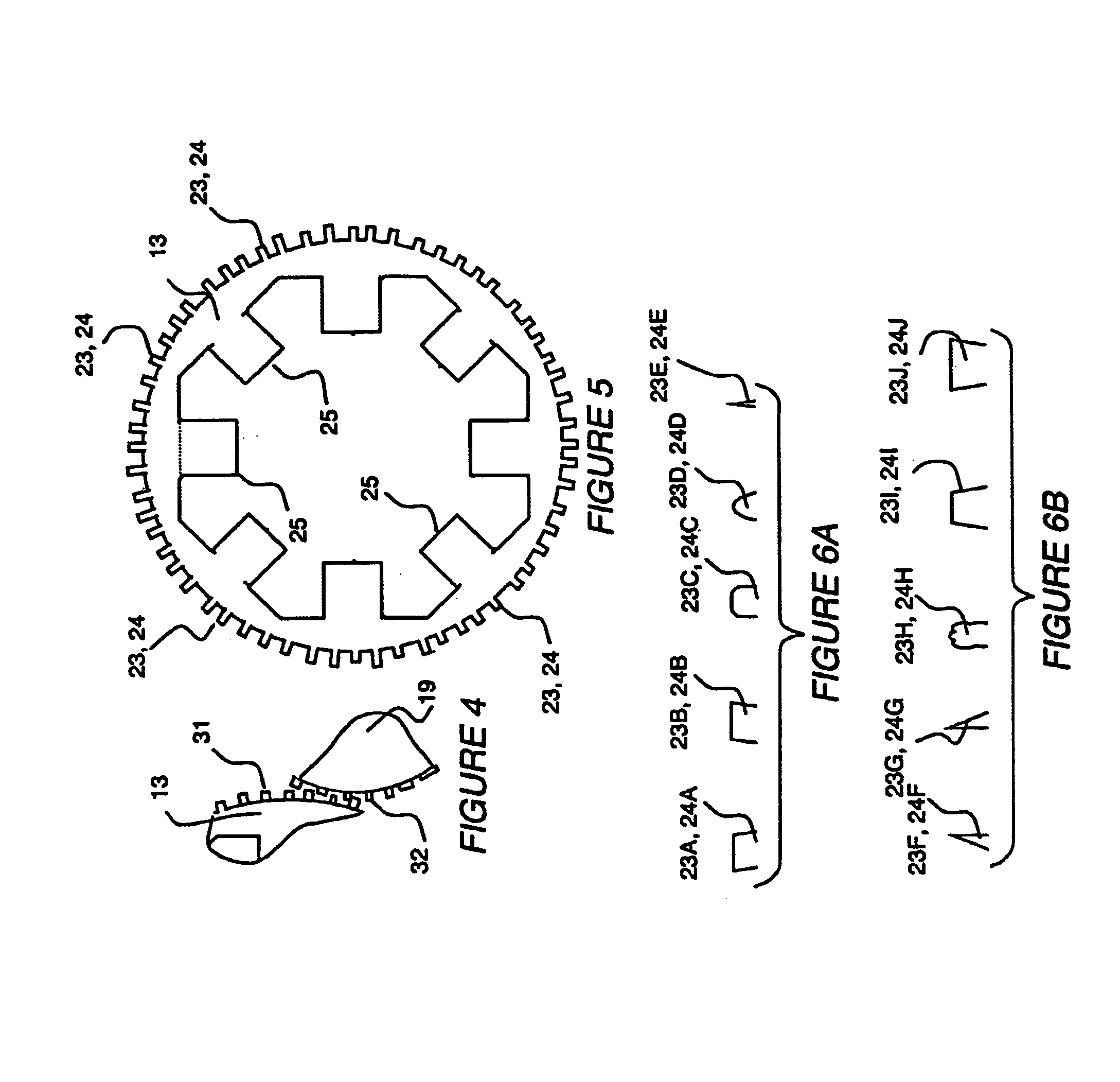
[0023]Each carriage 17 has a plurality of biased mountings 30, for example a combined lost-motion connection and compression spring mount 30 (not shown in detail), which biases freely rotatable driven wheels 18, 19 respectively into engagement with an adjacent one of the rotatable drive sh...


PUM


Abstract

An overhead rotatably powered conveyer drive shaft has ridges inter-engaged with skewed driven wheels mounted for free rotation on a load carrying carriage to trace a helical loci of engagement and improve traction. The ridges are preferably extruded to be parallel. The driven wheels may also have extruded parallel ridges or have an elastic peripheral surface deformed elastically into spaces between adjacent drive shaft ridges during normal conveying to provide the inter-engaging.

Description

BACKGROUND OF THE INVENTION[0001]1. Field of the Invention[0002]The field of the invention is that of overhead conveyers having fixed axis, rotatable drive shafts engaging skewed driven wheels of a carriage to provide the carriage conveying force, wherein the carriage is supported by the drive shaft and / or a fixed support rail.[0003]2. Description of the Related Art[0004]The present invention relates to overhead conveyors of the type disclosed in U.S. Pat. No. 5,806,655 issued Sep. 15, 1998 to Tabler, in U.S. Pat. No. 5,785,168 issued Jul. 28, 1998 to Beall, Jr., in U.S. Pat. No. 4,203,511 issued May 20, 1980 to Uhing, in U.S. Pat. No. 3,164,104 issued Jan. 5, 1965 to Hunt, and in U.S. Pat. No. 3,850,280 issued Nov. 26, 1974 to Ohrnell.[0005]Conventional rotating shaft driven overhead conveyors are limited in the amount of weight they may carry or the incline / decline they may traverse, without the carriage undergoing an uncontrolled slippage, particularly between the drive shaft and...

Claims


Application Information

Patent Timeline
Patent Type & Authority Patents(United States)
IPC IPC(8): B65G37/00
CPCB65G35/066B61B13/125
Inventor TABLER, CHARLES P.
Owner TABLER CHARLES P
Why Eureka
Try Eureka