
Radial fan

Active Publication Date: 2007-02-20
EBM PAPST LANDSHUT
View PDF17 Cites 28 Cited by
  • Summary
  • Abstract
  • Description
  • Claims
  • Application Information

AI Technical Summary

Benefits of technology

[0006]It is thus the object of the present invention to provide a radial fan that exhibits improvements vis-à-vis the known radial fans which are achieved by suitable means in all properties, e.g. by reducing the noise level while maintaining high efficiency.

Problems solved by technology

On the other hand, this arrangement prevents air expelled from the wheel to a great extent from reaching the supporting disk of the wheel which would reduce the efficiency of the air transport.

Method used


Image

  • Radial fan
  • Radial fan
  • Radial fan

Examples


Embodiment Construction

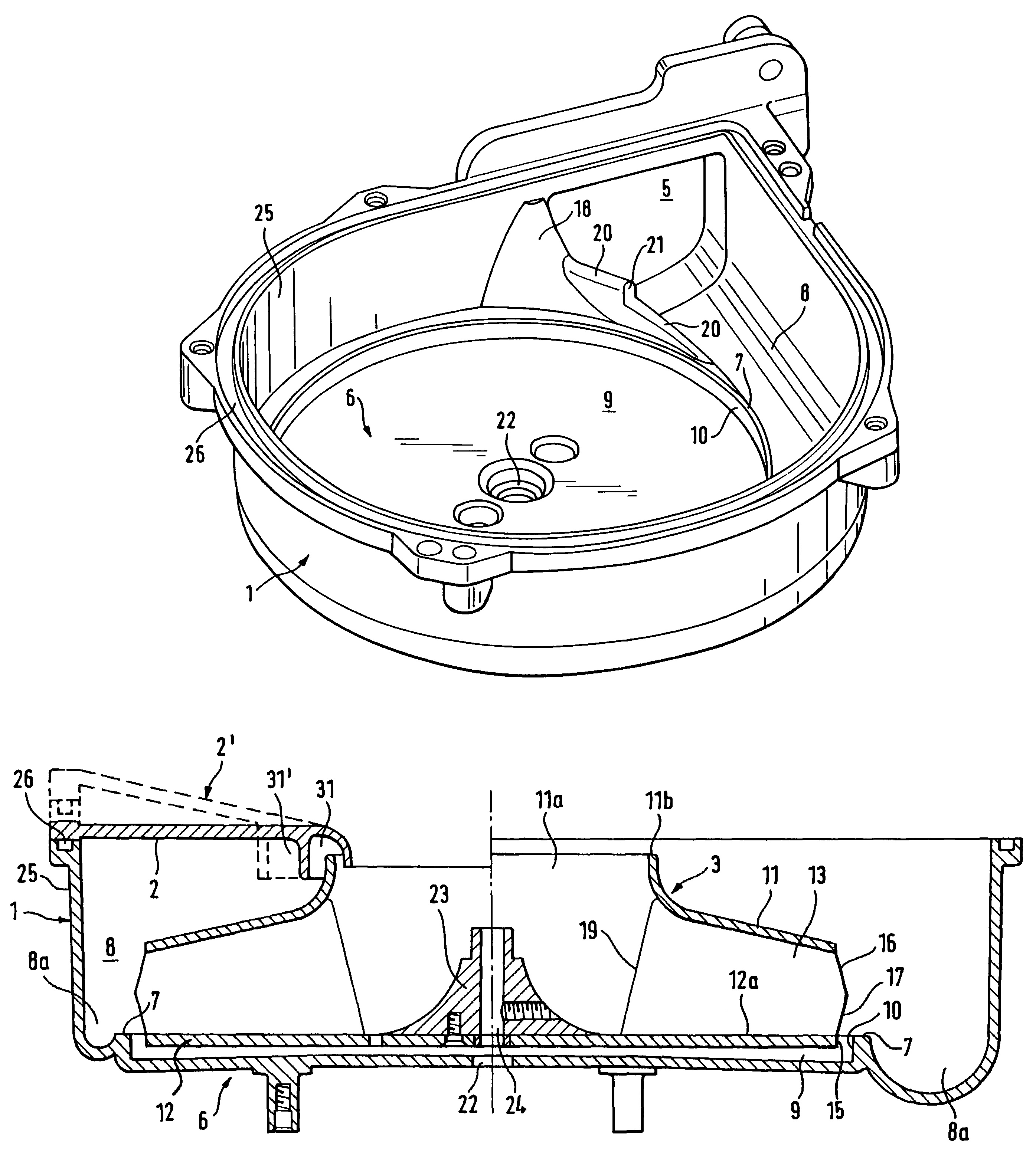
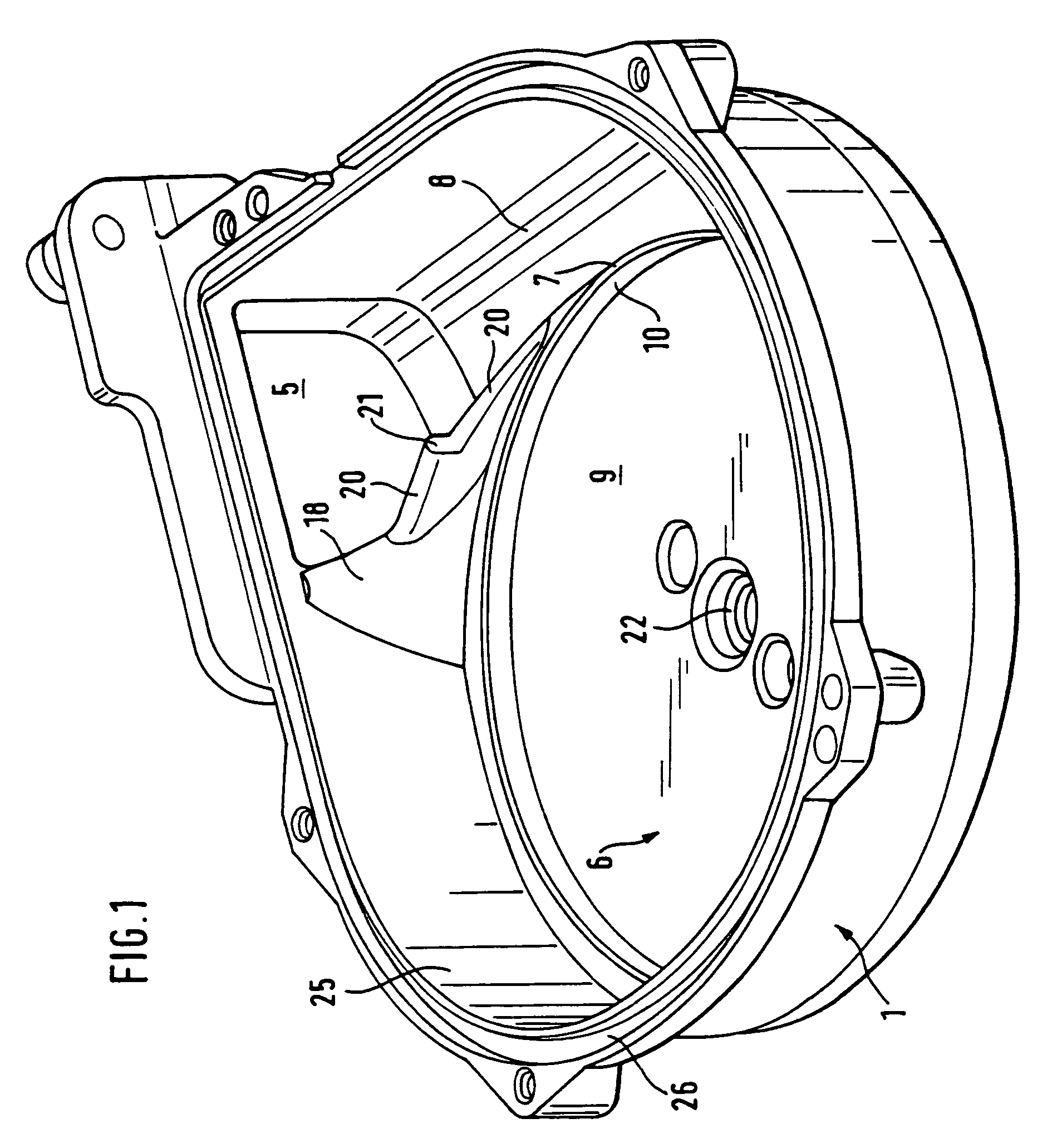
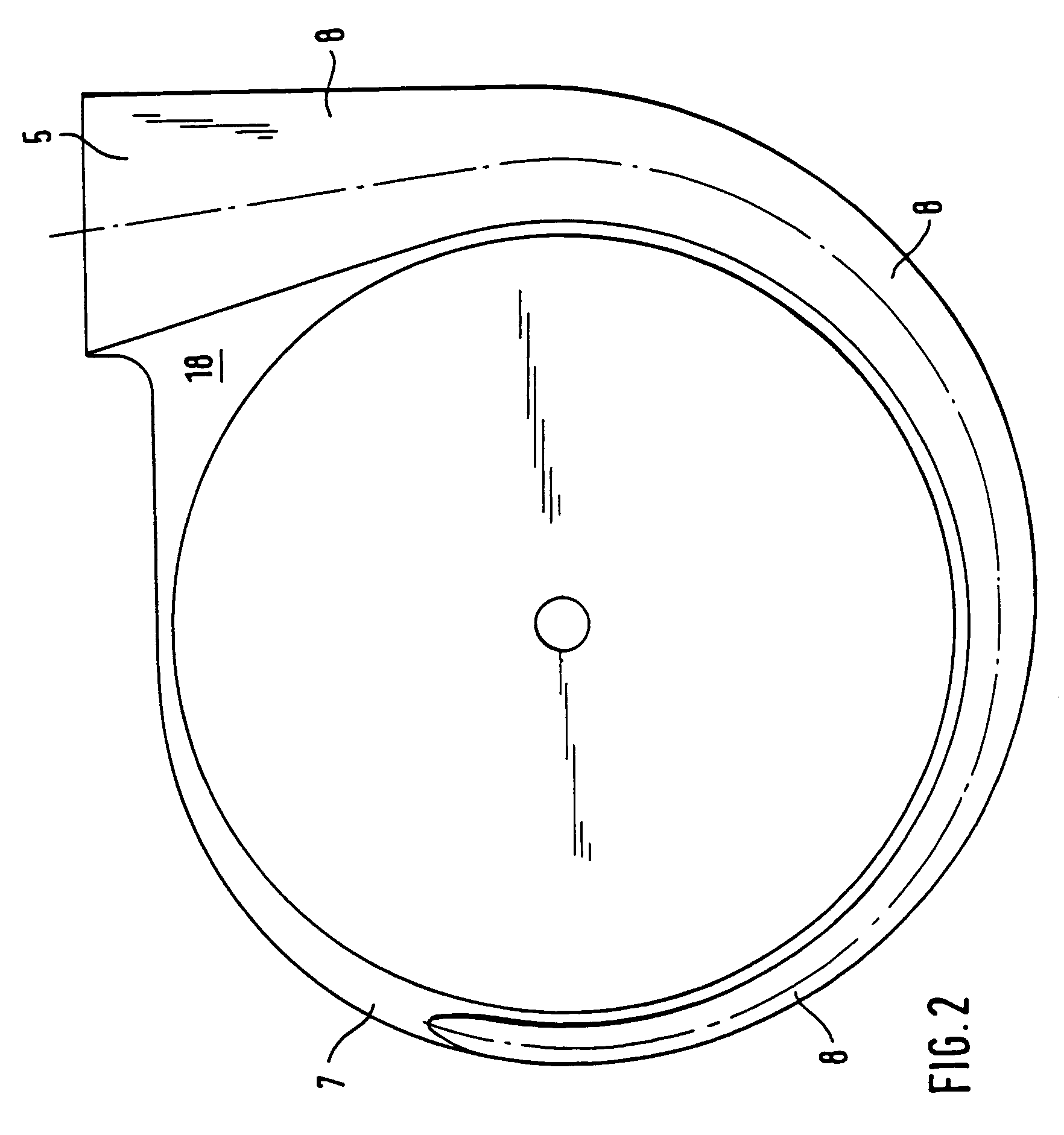
[0050]In FIG. 1, the casing 1 of a radial fan is shown in a perspective plan view of the interior. The radial fan has a detachable cover 2 (FIG. 3) on the casing as well as a fan wheel 3. The bottom section 6 of the casing 1 is surrounded by a spiral-shaped compression space 8. The compression space 8 is widest in a radial direction at an exhaust 5 and narrows in a spiral shape along the bottom section 6 as it extends away from the exhaust 5. In addition to the compression space 8, the bottom section 6 consists of the bottom reference surface 7 and a hollow cylindrical cup-like section 9 that is recessed relative to bottom reference surface 7 which in part is used to take up the wheel 3. An opening 22 in the axis of the bottom section 6 is used for the lead through of a driving shaft (not shown) to turn the wheel 3.

[0051]Also recessed vis-à-vis the bottom reference surface 7, i.e., extending beyond the reference surface in an axial direction, the compression space 8 has an axial ext...


PUM


Abstract

The invention relates to a radial fan with a casing and in it an axially placed wheel, wherein the casing has an axially placed air inlet, an exhaust (5), a bottom section (6) with a bottom reference surface (7) arranged orthogonally to the axis and a spirally shaped compression space located radially around the wheel that extends to the exhaust port; and wherein the wheel has a cover disk that faces the air inlet port and a supporting disk; wherein the radial fan is characterized in that the spiral-shaped compression space (8) expands both in a radial direction from the axis towards the exhaust port (6) as well as in an axial direction; wherein the axial expansion extends over at least 180° of the spiral circumference; and in which a hollow cylindrical cup-shaped section (9) is recessed in the bottom section (6) in an axial direction beyond the bottom reference surface (7) into which the wheel is placed in such a way that an inside of the supporting disk of the wheel runs flush with the bottom reference surface (7).

Description

FIELD OF THE INVENTION[0001]The invention relates to a radial fan with a casing and in it an axially placed air inlet, an exhaust, a radially and axially expanding compression space and a cylindrical hollow cup section for inserting a wheel.BACKGROUND OF THE INVENTION[0002]Radial-flow fans of this kind take in air, another gas such as methane or an air-gas mixture from a working environment and convey it whilst both the flow rate as well as the pressure of the medium transported rises.[0003]The primary intent of this type of fan is to improve the fan power performance characteristic and to adapt it to the desired application. There is also a great need for radial fans that at the specific fan power performance characteristic that is as high as possible at the same time produce little noise since these types of radial fans are frequently used in places in which noise is perceived as unpleasant. Various measures have been proposed in the state-of-the-art to improve the performance cha...

Claims


Application Information

Patent Timeline
IPC IPC(8): F04D29/42F04D29/30F04D29/28
CPCF04D29/4233F04D29/281
Inventor HOPFENSPERGER, REINHOLD
Owner EBM PAPST LANDSHUT
Features
  • Generate Ideas
  • Intellectual Property
  • Life Sciences
  • Materials
  • Tech Scout
  • Unparalleled Data Quality
  • Higher Quality Content
  • 60% Fewer Hallucinations
Learn More