RF induction lamp with reduced electromagnetic interference

a technology of electromagnetic interference and induction lamp, which is applied in the direction of gas-filled discharge tubes, magnetic discharge control, gaseous cathodes, etc., can solve the problems of reducing the efficiency of lamps, limiting the places where lamps can be used, and increasing the cost of lamps, so as to improve the electrostatic symmetry of lamps

Inactive Publication Date: 2007-02-20
OSRAM SYLVANIA INC
View PDF5 Cites 30 Cited by
  • Summary
  • Abstract
  • Description
  • Claims
  • Application Information

AI Technical Summary

Benefits of technology

[0009]It is still another object of the invention to enhance the efficiency of electrodeless fluorescent lamps.
[0011]These objects are accomplished, in one aspect of the invention, by an electrodeless fluorescent lamp having a lamp envelope that includes a chamber with core of magnetic material therein. A first winding surrounds the core and has a first hot lead-in wire attached to a high frequency end of the voltage supply and a second lead-in connected to the local ground of the RF voltage supply. A second winding surrounds the core, and respective turns of the second winding are located adjacent turns of the first winding and electrically insulated therefrom. The second winding has a free end and has another end connected to one of the grounded lead-in wires of the first winding. A grounded braided sheath surrounds the hot lead-in wire of the first winding. The first winding and the second winding are bifilar and have equal lengths. This construction improves the electrostatic symmetry of the lamp by screening the lead-in wire of the driven winding.

Problems solved by technology

Such fixtures function as a Faraday shield and allow the lamp to operate without too much disturbance to adjacent devices; however, such special fixtures also limit the places where the lamps can be employed.
This system greatly increases the cost of the lamp and reduces the lamps efficiency and is really only suitable for PAR lamps.

Method used


Image

  • RF induction lamp with reduced electromagnetic interference
  • RF induction lamp with reduced electromagnetic interference
  • RF induction lamp with reduced electromagnetic interference

Examples


Embodiment Construction

[0018]For a better understanding of the present invention, together with other and further objects, advantages and capabilities thereof, reference is made to the following disclosure and appended claims taken in conjunction with the above-described drawings.

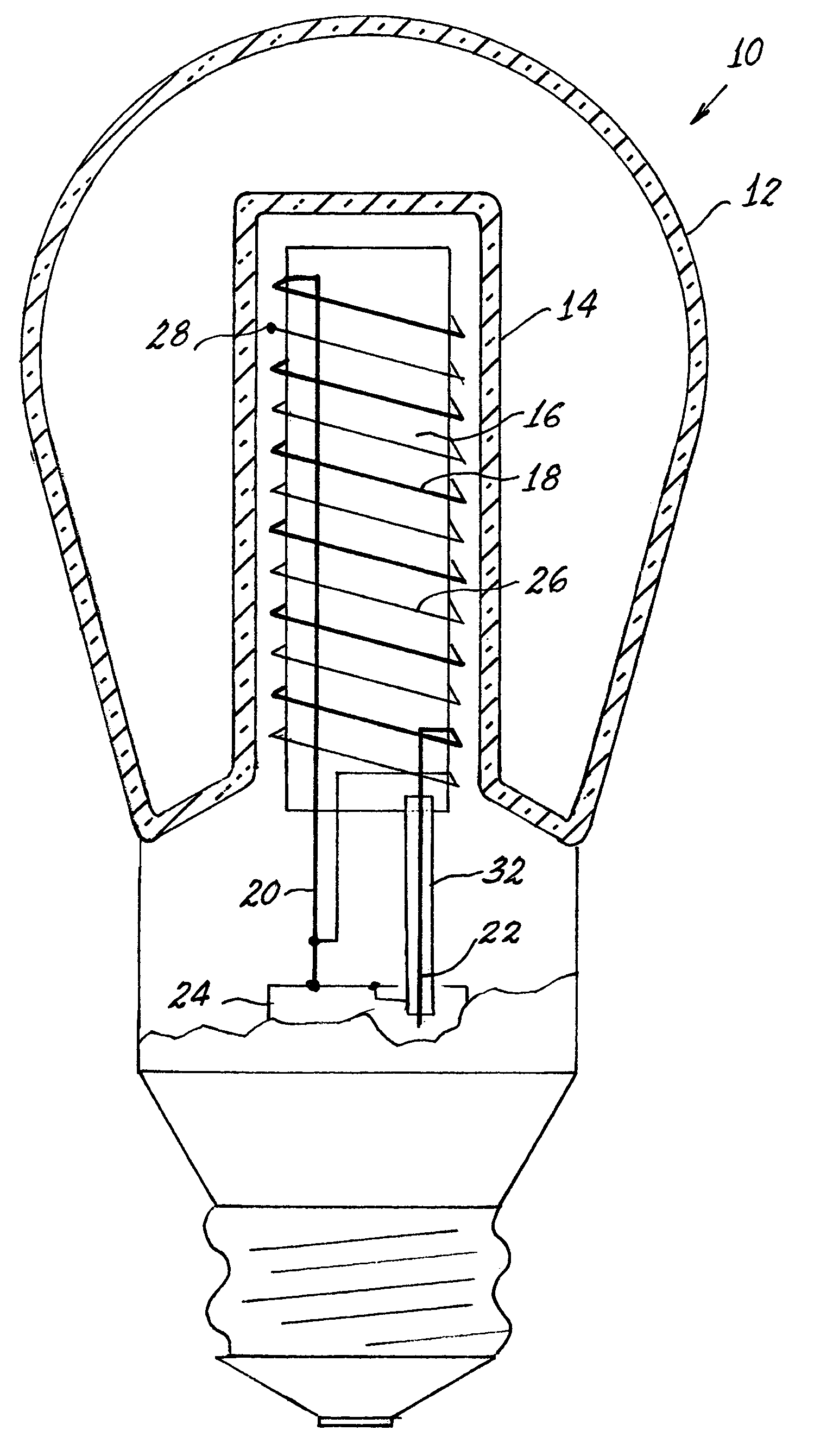
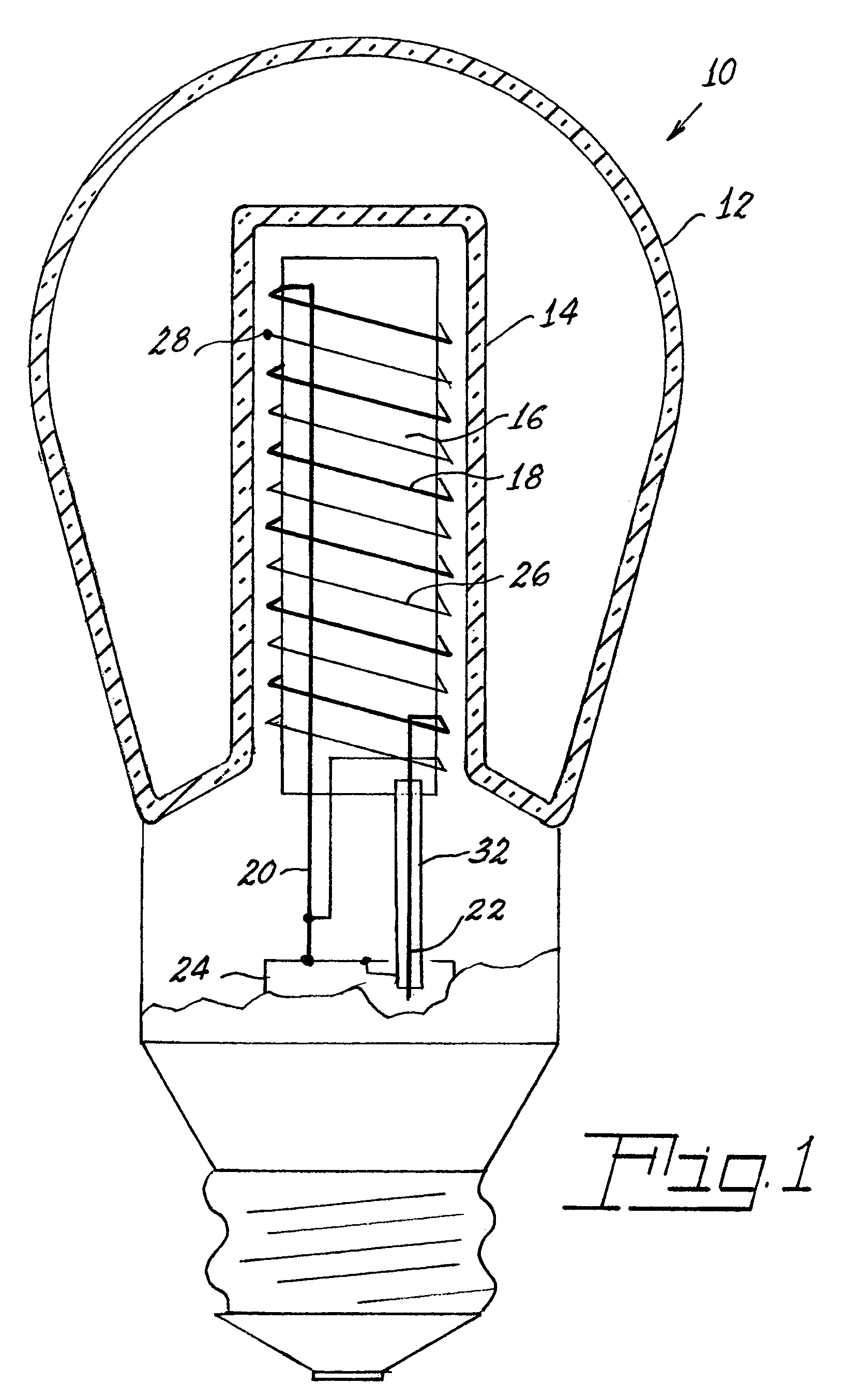
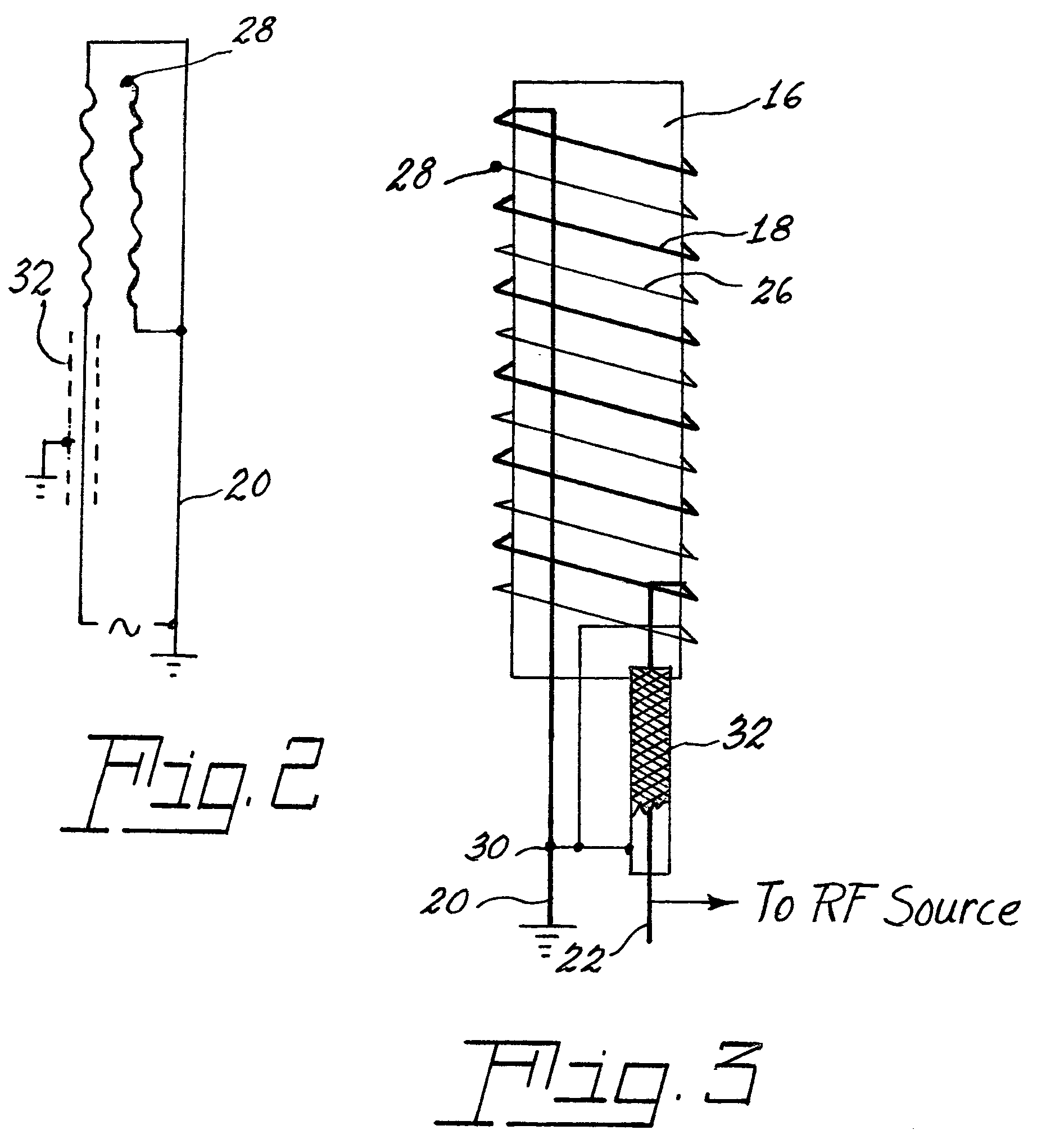
[0019]Referring now to the drawings with greater particularity, there is shown in FIG. 1 an electrodeless fluorescent lamp 10 having an envelope 12 that includes a chamber 14. A core 16 of magnetic material, preferably ferrite, is positioned in the chamber 14 and has a first winding 18 surrounding the core and having first and second lead-in wires 20, 22, attached to a high frequency voltage supply or ballast 24. A second winding 26 surrounds the core 16, respective turns of the second winding 26 being located adjacent turns of the first winding 18 and electrically insulated therefrom. The second winding 26 has a free end 28 and has another end 30 connected to one of the lead-in wires, for example 20. A braided sheath 32 (shown s...


PUM


Abstract

An electrodeless fluorescent lamp 10 has an envelope 12 that includes a chamber 14. A core 16 of magnetic material, preferably ferrite, is positioned in the chamber 14 and has a first winding 18 surrounding the core and having first and second lead-in wires 20, 22, attached to a high frequency voltage supply or ballast 24. A second winding 26 surrounds the core 16, respective turns of the second winding 26 being located adjacent turns of the first winding 18 and electrically insulated therefrom. The second winding 26 has a free end 28 and has another end 30 connected to one of the lead-in wires, for example 20. A braided sheath 32 surrounds the other of the lead-in wires 22. The first winding 18 is generally called the RF antenna. The braided sheath 32 is connected to the local ground. This inexpensive solution alone reduces the conductive EMI level sufficiently to pass all existing regulations on such interference with significant reserve.

Description

CROSS-REFERENCES TO RELATED APPLICATIONS[0001]This application claims priority from Provisional Patent Application No. 60 / 563,088 filed on Apr. 16, 2004.TECHNICAL FIELD[0002]This invention relates to electrodeless fluorescent lamps and more particularly to such lamps having reduced electromagnetic interference (EMI) making them more suitable for the commercial and residential markets.BACKGROUND ART[0003]Electrodeless fluorescent lamps generally require mounting in a special fixture designed to shield the surrounding area from the EMI generated by the operation of the lamp. Such fixtures function as a Faraday shield and allow the lamp to operate without too much disturbance to adjacent devices; however, such special fixtures also limit the places where the lamps can be employed.[0004]Several current lamps attempt to solve this problem by various means, one of which involves applying EMI screening to the lamp envelope in the form of a transparent conductive coating on the interior sur...

Claims


Application Information

Patent Timeline
Patent Type & Authority Patents(United States)
IPC IPC(8): H01J29/76H01J1/50H01J65/04
CPCH01J65/048H01J65/04
Inventor GODYAK, VALERY A.ALEXANDROVICH, BENJAMIN M.SAPOZHNIKOV, ALEXANDER A.
Owner OSRAM SYLVANIA INC
Why Eureka
Try Eureka