Triac-based, low voltage AC dimmer

Inactive Publication Date: 2007-02-20
GANNON HENRY MICHAEL
View PDF6 Cites 78 Cited by
  • Summary
  • Abstract
  • Description
  • Claims
  • Application Information

AI Technical Summary

Benefits of technology

[0008]It would therefore be advantageous to provide a two-wire triac-based low voltage AC dimmer adapted for configuration in series with a typically incandescent lighting load. In accordance with the illustrated preferred embodiment of the present invention, a step-down transformer provides a low voltage AC waveform, and a separate, electrically isoated loop circuit utilizing a step-up transformer converts a portion of the low voltage AC waveform into a corresponding high voltage AC waveform used to trigger the gate of a triac

Problems solved by technology

SCR dimmers are disadvantageous in that two devices in combination with an elaborate triggering arrangement are required in full wave AC applications.
Since triacs require a relatively high trigger voltage on the order of 35 volts, their prior art usage has been largely limited to line voltage AC applications.
The principal disadvantage of prior art triac-based line voltage AC dimmers is the generation of a relatively high level of undesirable radio frequency noise that results from the inherently rapid switching time of the triac.
Yet another disadvantage of triac-based line voltage AC dimmers is the potential for light flickering and unwanted extinguishing of the incandescent lighting load at or near the maximum dimming level.
A major drawback of low voltage AC lighting as compared with line voltage lighting is that it requires proportionally more current to obtain the same level of illumination, thereby placing an increased strain on current-carrying components.
However, a triac-based line voltage AC dimmer is an acknowledged poor device for driving the inductive load presented by the primary side of a transformer because the inherent fast switching time of the tr

Method used


Image

  • Triac-based, low voltage AC dimmer
  • Triac-based, low voltage AC dimmer
  • Triac-based, low voltage AC dimmer

Examples


Example

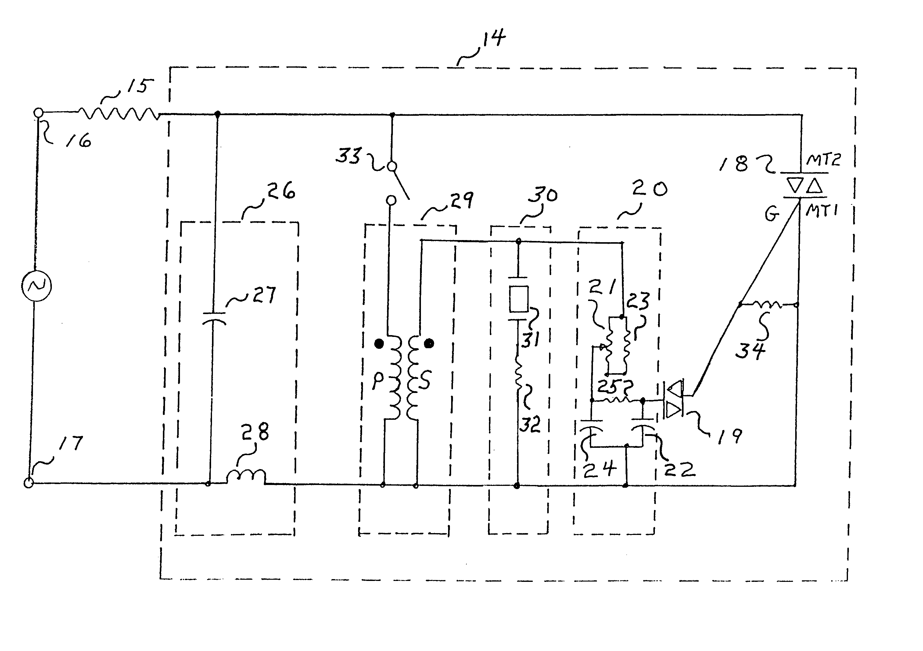
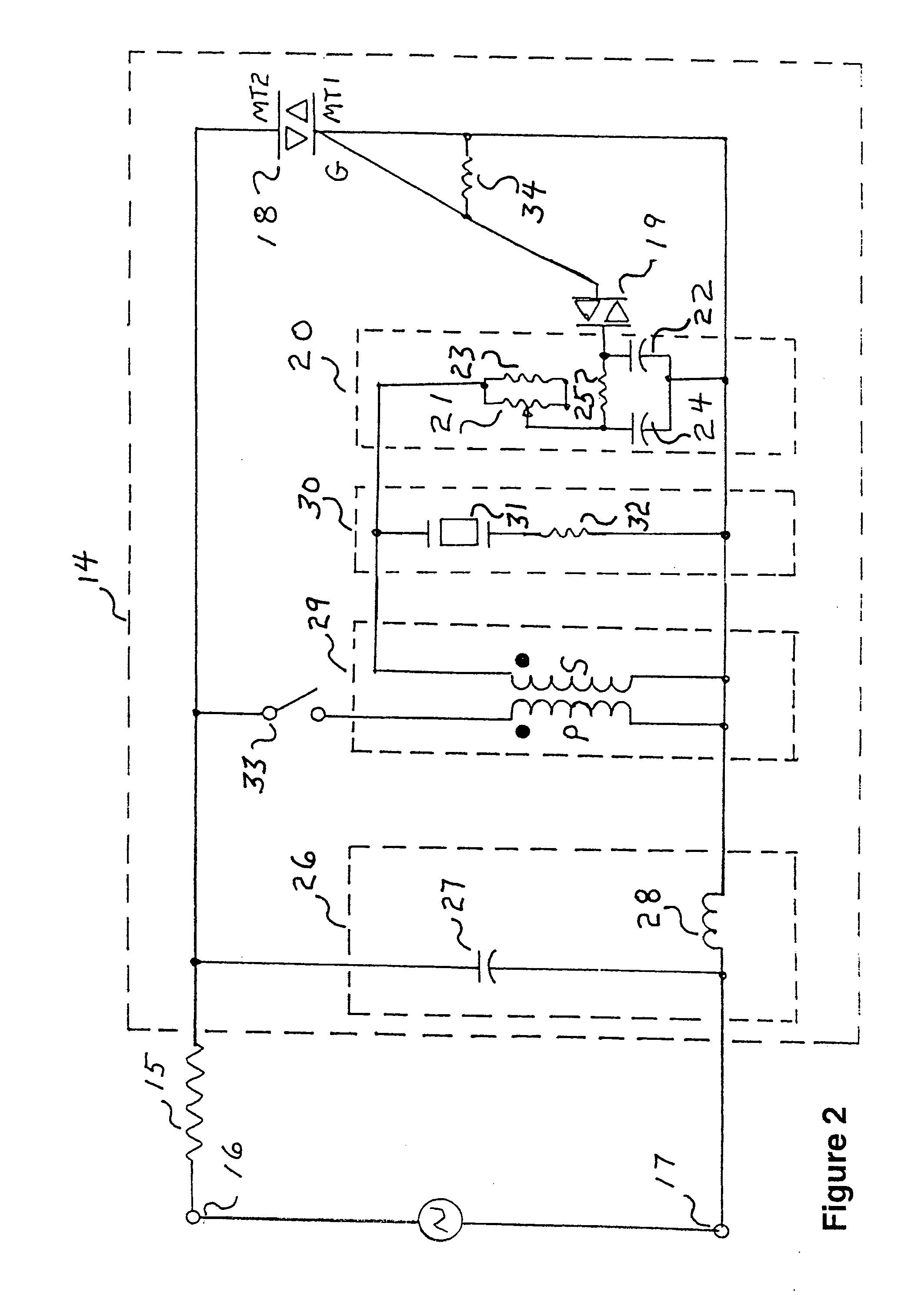
[0011]FIG. 2 shows a triac-based, low-voltage AC dimmer circuit 14 constructed in accordance with the present invention. Dimmer circuit 14 is configured in series with an incandescent lighting load 15 as a complete controller and load circuit. An external source of low-voltage AC, typically provided at the secondary winding of a standard step-down transformer, is applied to the circuit across input terminals 16 and 17. All component values stated hereinafter are nominal and approximate.

[0012]A triac 18 may comprise any commercially available triac device. Triggering for the on or conductive state is achieved by applying a threshold voltage of either polarity across gate G and the MT1 power terminal, as low-voltage is concurrently applied across the MT1 and MT2 power terminals. Once triggered, current flows through the MT1 and MT2 power terminals to energize incandescent load 15. Triac 18 reverts to its off or blocking state whenever the voltage across the MT1 and MT2 power terminals...


PUM


Abstract

A two-wire triac-based low voltage AC dimmer adapted for configuration in series with a typically incandescent lighting load. An external step-down transformer provides a source of low AC voltage, and a separate, electrically isoated loop circuit utilizing a step-up transformer converts a portion of the low AC voltage into a corresponding high AC voltage used to trigger the gate of a triac. An on/off arrangement that serves to lock the triac in its blocking may optionally be provided. A shunting resistor connected across the triac serves to dissipate static charge buildup that may otherwise falsely trigger the triac to its on state. A phi filter provides a smoother and more regulated triggering pulse to the triac, thereby minimizing or eliminating flickering and undesirable extinguishing of the incandescent lighting load at low brightness settings.

Description

FIELD OF THE INVENTION[0001]The present invention relates generally to AC dimmers and, more particularly, to a triac-based low voltage dimmer for use in outdoor applications such as architectural lighting and swimming pool lighting, for example.BACKGROUND AND SUMMARY OF THE INVENTION[0002]Dimmers of various types are well known in the prior art. Mechanical rheostats must dissipate considerable wasted energy in the form of heat and must be closely coordinated in resistive value with the load being controlled in order to achieve optimal dimming effect. SCR dimmers are disadvantageous in that two devices in combination with an elaborate triggering arrangement are required in full wave AC applications. The triac has been the device of choice in prior art line voltage AC dimmers due to its inherently high efficiency and load independence. Since triacs require a relatively high trigger voltage on the order of 35 volts, their prior art usage has been largely limited to line voltage AC appl...

Claims


Application Information

Patent Timeline
IPC IPC(8): H05B41/16H05B37/02
CPCH05B39/044Y02B20/146Y02B20/00
Inventor GANNON, HENRY MICHAEL
Owner GANNON HENRY MICHAEL
Why Eureka
Try Eureka