Control system and method for electric drives with a.c. motors

a control system and motor technology, applied in the direction of dynamo-electric machines, single motor speed/torque control, synchronous motor starters, etc., can solve the problems of increasing the overall dimension of the drive, contributing significantly, increasing the cost of the drive, etc., and achieve the effect of more robustness

Inactive Publication Date: 2007-02-20
UNIVERSITY OF CATANIA
View PDF6 Cites 27 Cited by
  • Summary
  • Abstract
  • Description
  • Claims
  • Application Information

AI Technical Summary

Benefits of technology

[0015]As compared with other sensorless techniques based upon the injection of test signals, and in particular of high-frequency signals, the technique proposed is more robust, does not require installation of further current and voltage sensors and can be in theory used on all a.c. electric machines, whether anisotropic ones or isotropic ones, provided, however, that in the latter case the intensity of the main flux is able to saturate the ferromagnetic core.

Problems solved by technology

Installation of said sensors causes an increase in the overall dimensions of the drive, renders necessary supplementary wiring and contributes considerably to increasing the cost of the drive.
Furthermore, in particular operating conditions, the delicacy of such sensors can adversely affect the reliability of the drive.
The disadvantages linked to installation of the aforesaid sensors have been an impulse to the development of a series of vector-control techniques, referred to as “sensorless” techniques, which are able to reconstruct the position of the rotor flux without using a position transducer.
The techniques based upon said principle can be implemented simply and at a low cost; however, they do not function at low or zero rotor speeds.
However, they also prove extremely expensive in terms of computing power required and / or in terms of processing times and, in many cases, do not provide a complete solution to the problem of vector control of a.c. electric machines at very low or zero speeds.

Method used


Image

  • Control system and method for electric drives with a.c. motors
  • Control system and method for electric drives with a.c. motors
  • Control system and method for electric drives with a.c. motors

Examples


Embodiment Construction

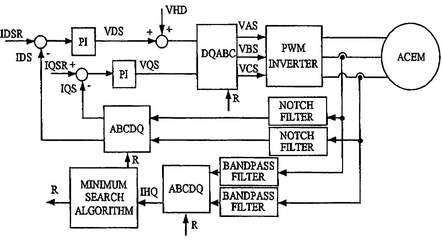
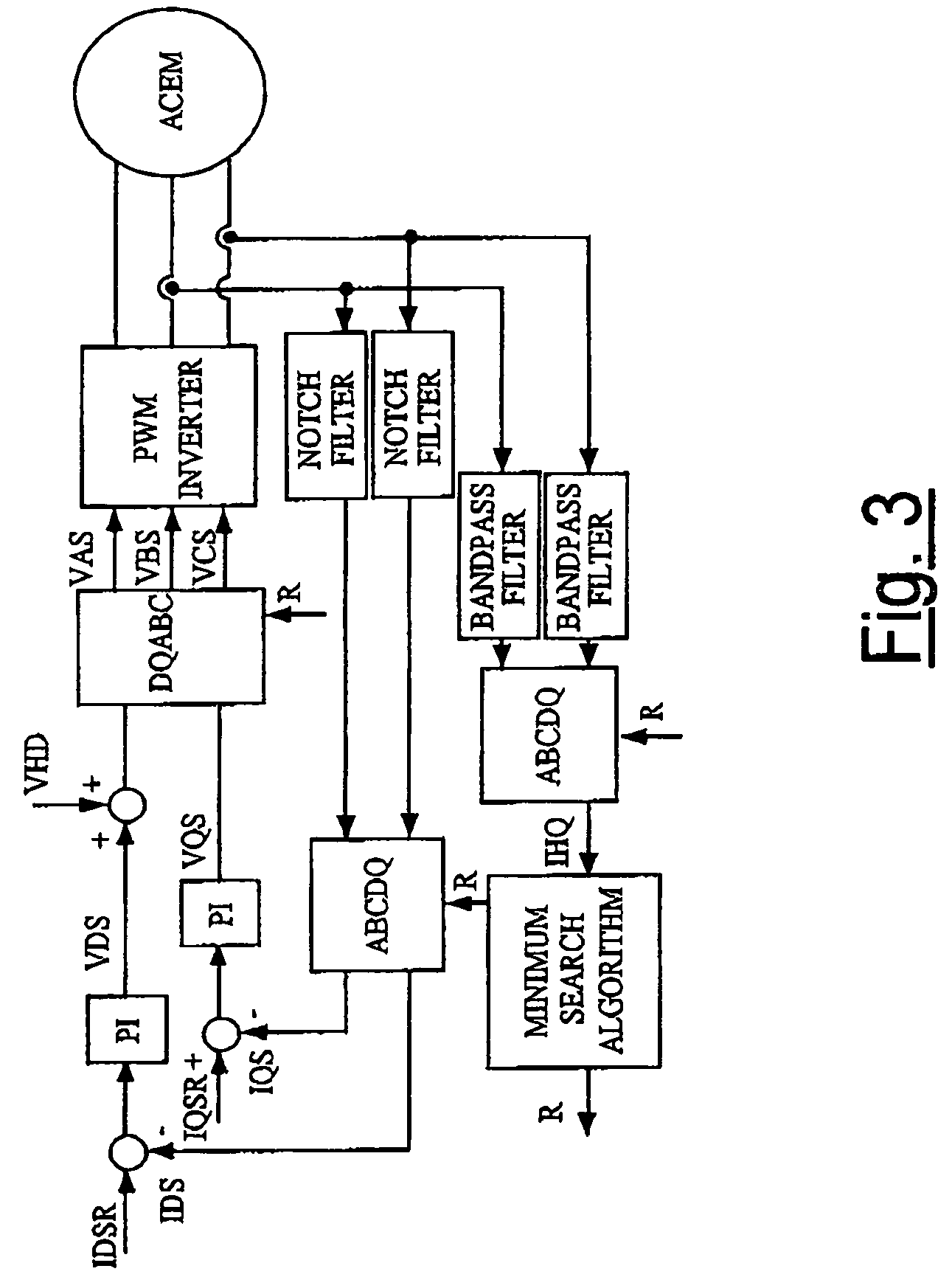
[0020]The control method according to the invention is suited to a simple and economic experimental implementation such as the one illustrated in the block diagram of FIG. 3, which represents an exemplifying, but non-limiting, embodiment of the system according to the invention. Present in said figure are three blocks that perform a transformation of reference axes, and in particular two blocks of the type ABCDQ, which enable passage from the fixed reference system ABC to the rotating system DQ, and a block DQABC, which performs the reverse operation. Further present are two regulation blocks PI, which process the current error and generate the signals VDS, VQS, which are then transformed into the references VAS, VBS and VCS of the PWM INVERTER that supplies the a.c. electric machine ACEM.

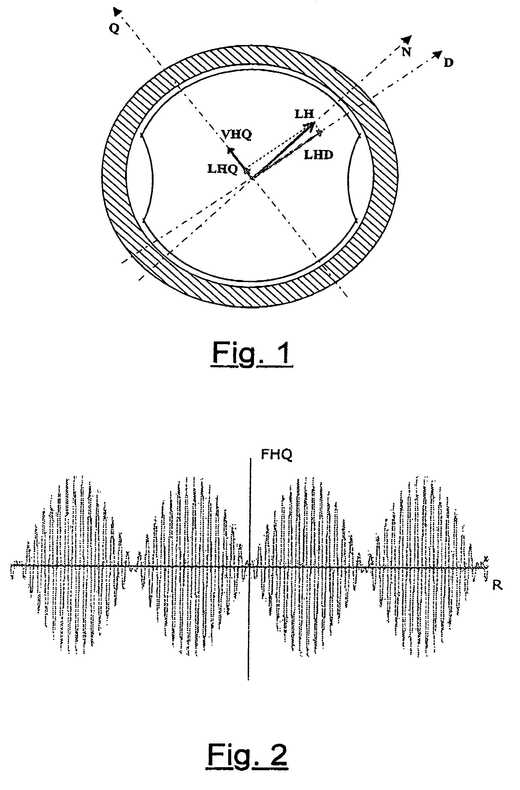
[0021]With reference to the above figures, VHQ designates the voltage induced by the flux component LHQ. Said flux component is, in turn, generated by the additional oscillating field FH, is orthog...


PUM


Abstract

A vector-control system and method of a “sensorless” type for electric drives with a.c. motors is based upon generation of an oscillating magnetic field and upon measurement of the deviation, with respect to said oscillating field, of the flux generated thereby on account of anisotropy, whether natural or induced, of the magnetic structure of the machine.

Description

BACKGROUND OF THE INVENTION [0001]1. Field of the Invention[0002]Forming the subject of the present invention are a control system and a control method for “sensorless” drives with a.c. motors.[0003]Currently, vector-controlled electric drives with a.c. motors are widely used in various industrial applications, in machine tools, pumps, conveyor belts, and the like, where they are progressively supplanting traditional d.c. electric drives, thanks also to their greater sturdiness, their reduced maintenance requirements, and their lower production costs.[0004]2. Description of the Prior Art[0005]The principle of vector control is based on the independent regulation of the components of the stator-current vector defined with respect to a reference system synchronous with the rotor flux. The instantaneous position of the rotor flux, which is necessary for vector control, can be measured directly using Hall-effect flux sensors or, in the case of synchronous machines, by measuring the posi...

Claims


Application Information

Patent Timeline
Patent Type & Authority Patents(United States)
IPC IPC(8): H02P6/08H02P27/00H02P21/00H02P21/05
CPCH02P6/183H02P6/185H02P21/05H02P21/0053H02P2203/11H02P21/32
Inventor CONSOLI, ALFIOSCARCELLA, GIUSEPPETESTA, ANTONIO
Owner UNIVERSITY OF CATANIA
Why Eureka
Try Eureka