Synchronous motor control method and device

a synchronous motor and control method technology, applied in the direction of motor/generator/converter stopper, dynamo-electric converter control, mechanical energy handling, etc., can solve the problem of inability to drive efficiently, inability to achieve sufficient vibration suppression effect, and inability to follow high speed variation, so as to prevent or greatly suppress the speed variation of the synchronous motor. , the effect of improving controllability

Inactive Publication Date: 2007-02-20
DAIKIN IND LTD
View PDF39 Cites 29 Cited by
  • Summary
  • Abstract
  • Description
  • Claims
  • Application Information

AI Technical Summary

Benefits of technology

[0078]Therefore, the apparatus can sufficiently follow the high speed variation, and can prevent or greatly suppress the speed variation of the synchronous motor. As a result, the apparatus realizes improvement in controllability, improvement in voltage utilization rate, decrease in noise, sufficient suppression in vibration, and improvement in efficiency, with little effect on the motor characteristics.
[0079]When the apparatus for controlling synchronous motor of an embodiment is employed, the apparatus employs means for using fixed coordinate motor model, for calculating flux by integrating the motor voltage, and for calculating the rotational position from the rotational position information of the rotor included within the flux, as the rotational position calculation means. Therefore, the apparatus can sufficiently follow the high speed variation, and can prevent or greatly suppress the speed variation of the synchronous motor. As a result, the apparatus realizes improvement in controllability, improvement in voltage utilization rate, decrease in noise, sufficient suppression in vibration, and improvement in efficiency, with little effect on the motor characteristics.
[0080]When the apparatus for controlling synchronous motor of an embodiment is employed, the apparatus employs a motor having magnetic salient pole as the synchronous motor, and which employs means for calculating a rotational position using higher harmonics of input voltage and higher harmonics of current as the rotational position calculation means. Therefore, the apparatus can carries out the rotational position detection without error for rapid load variation.

Problems solved by technology

When the method (1) is employed, a voltage utilization rate cannot be improved because current controlling is employed.
Therefore, sufficient suppression effect in vibration cannot be obtained even when the torque controlling is carried out for suppressing speed variation within one rotation.
Also, controllable range in voltage phase is small so that IPM (brush-less DC motor having a rotor which has magnet embedded arrangement) cannot be driven with efficiency.
Further, it is difficult for the controlling to be made accurate because only rotational position detection at every 60 degrees can be carried out.

Method used


Image

  • Synchronous motor control method and device
  • Synchronous motor control method and device
  • Synchronous motor control method and device

Examples


Embodiment Construction

[0110]Hereinafter, referring to the attached drawings, we explain embodiments of a synchronous motor controlling method and apparatus thereof according to embodiments of the present invention in detail. In each of the following embodiments, cases are explained in which output voltages of an inverter are controlled. But, it is possible that output currents of an inverter can be controlled.

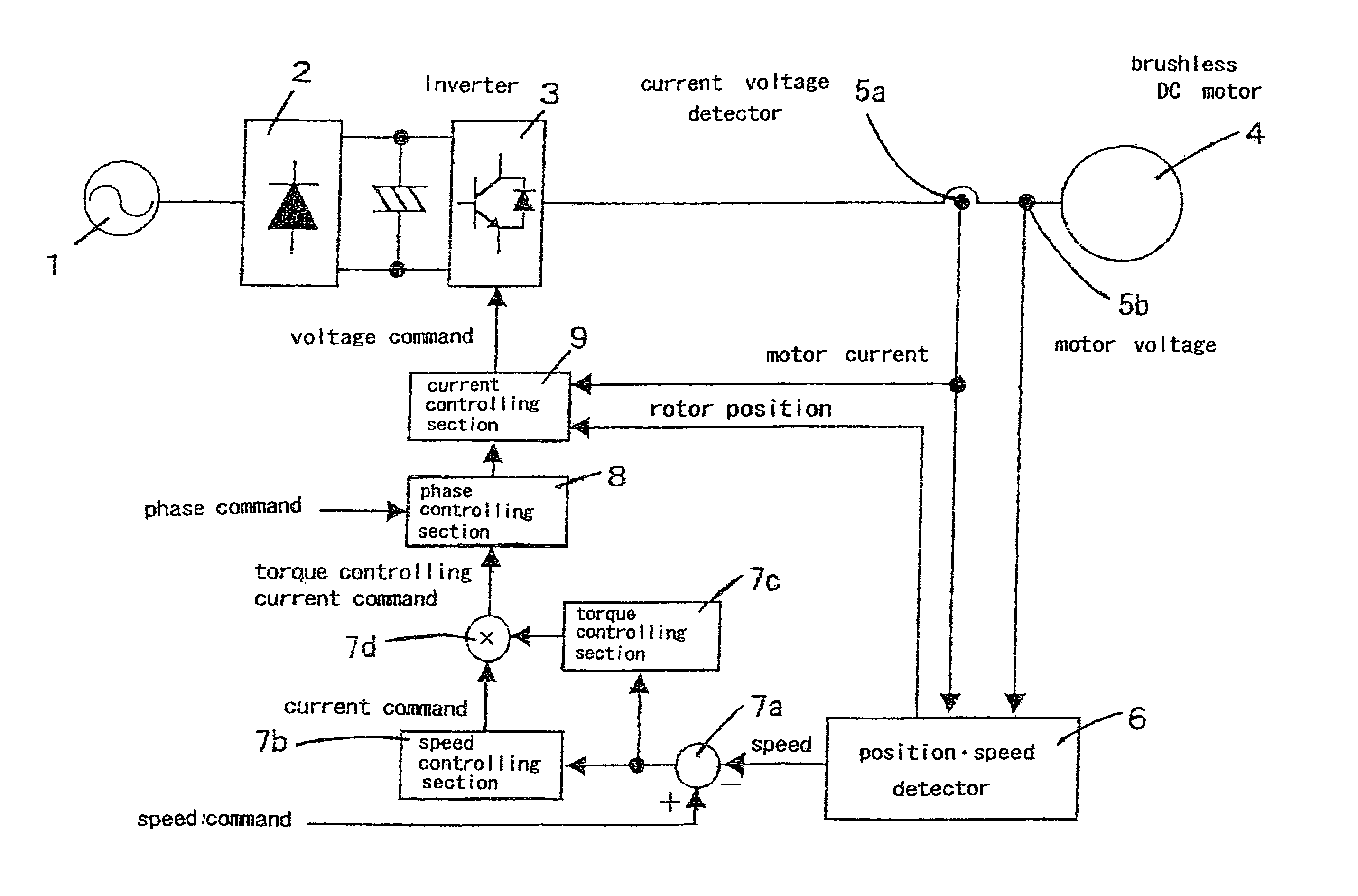
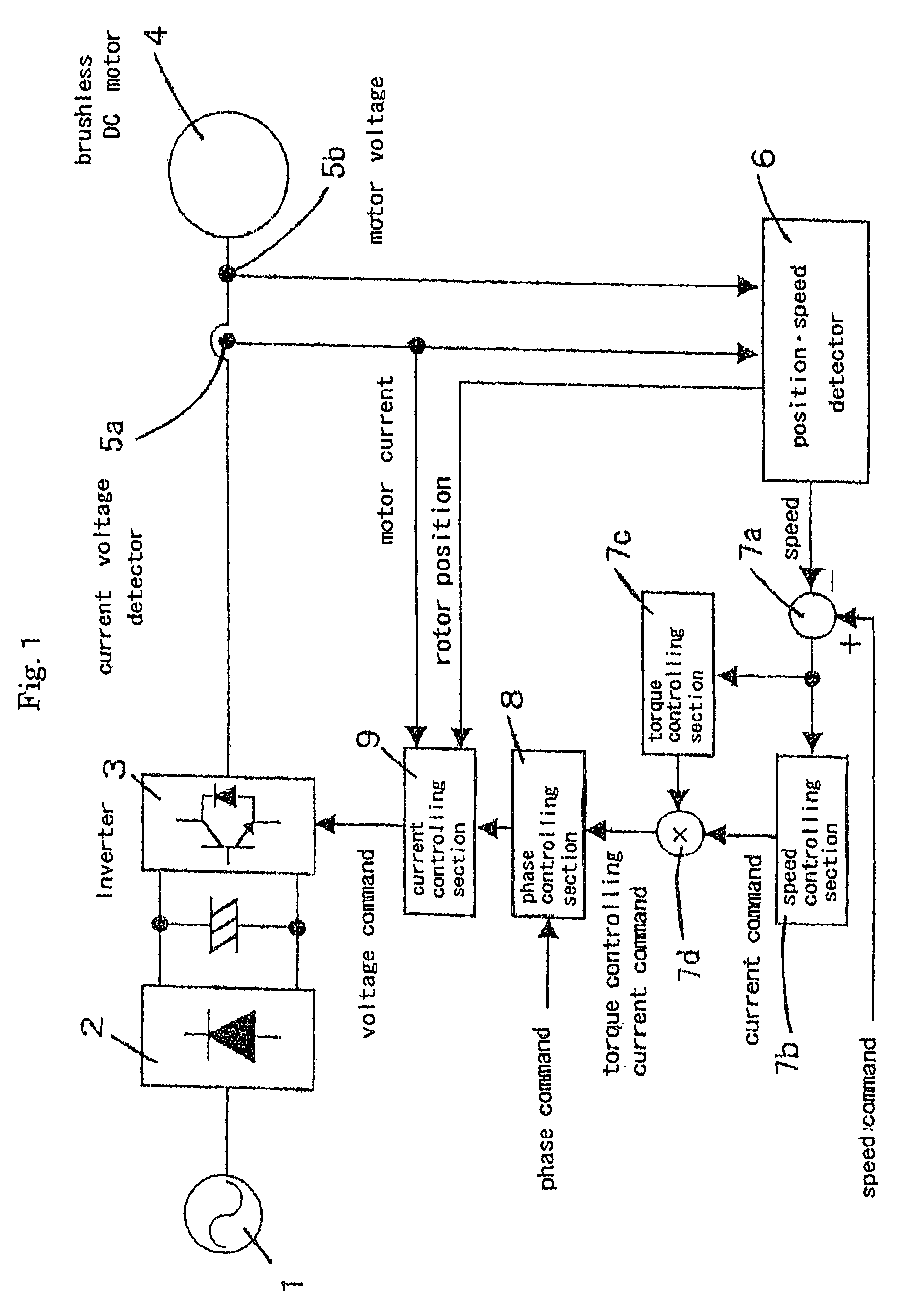
[0111]FIG. 1 is a block diagram illustrating a synchronous motor controlling apparatus of an embodiment according to the present invention.

[0112]This synchronous motor controlling apparatus comprises a converter 2, inverter 3, current detection section 5a, voltage detection section 5b, position and speed detection section 6, speed difference calculation section 7a, speed controlling section 7b, torque controlling section 7c, multiplication section 7d, phase controlling section 8, and current controlling section 9.

[0113]The converter 2 receives AC source 1 as input and outputs DC power.

[0114]The inve...


PUM


Abstract

Synchronous motor controlling apparatus and method controls power applied to minimize or eliminate speed variations of a synchronous motor due to variations in load imposed the motor. The rotational position of a rotor of the synchronous motor based on the input terminal voltages and currents to the synchronous motor, and the power applied to the motor is adjusted accordingly. Higher harmonics of the input voltages and currents may also be used to detect the position of the rotor. In addition, the apparatus and method also accounts for the varying speed command inputs.

Description

[0001]This application is the national phase under 35 U.S.C. § 371 of PCT International Application No. PCT / JP01 / 09855 which has an International filing date of Nov. 9, 2001, which designated the United States of America.TECHNICAL FIELD[0002]The present invention relates to a method and apparatus for controlling a synchronous motor. More particularly, the present invention relates to a novel method and apparatus for controlling a synchronous motor which detect a rotational position of a rotor using a motor model, and control the synchronous motor accurately even when load, speed command value and torque command vary.RELATED ART [0003]From the past, a synchronous motor is employed as a driving source of each of various species of devices. Improvement in voltage utilization rate {enlargement in driving range (due to over modulation}, realizing high efficiency, improvement in controllability, realizing low noise} is: required for such synchronous motor. Also, improvement in reliability...

Claims


Application Information

Patent Timeline
Patent Type & Authority Patents(United States)
IPC IPC(8): H02P6/00H02K7/00H02P6/08H02P6/10
CPCH02P6/002H02P25/083H02P6/10H02P6/085H02P6/28H02P25/089
Inventor MAEDA, TOSHIYUKIKOSAKA, MANABUKITA, MASANOBU
Owner DAIKIN IND LTD
Why Eureka
Try Eureka