Al technical title is built by PatSnap Al team. It summarizes the technical point description of the patent document.
a dual-band antenna and matching technology, applied in the field of wireless communication antennas, can solve the problems low design efficiency, and insufficient design to cover all the required frequencies, and achieve the effects of reducing the loss of ferroelectric components, reducing the cost of cellular band performance, and improving gps and pcs performan
Inactive Publication Date: 2007-02-20
KYOCERA CORP
View PDF184 Cites 373 Cited by
Summary
Abstract
Description
Claims
Application Information
AI Technical Summary
This helps you quickly interpret patents by identifying the three key elements:
Problems solved by technology
Method used
Benefits of technology
[0021]In one aspect, tuning is achieved by: supplying first and second control voltages, respectively, to the first and second tuning circuits; and, adjusting the dielectric constant of a ferroelectric (FE) dielectric material in response to the control voltages. For example, the first tuning circuit ma...
Problems solved by technology
Such a design is not always adequate to cover all the required frequencies (communication bands), however.
However, the widening of the higher band, to improve GPS and PCS performance, comes at the expense of cellular band performance.
Conventional measurement techniques, however, have characterized ferroelectric components as substantially lossy, regardless of the processing, doping or other fabrication techniques used to improve their loss properties.
Ferroelectric tunable components operating in RF or microwave regions are perceive...
Method used
Image
Click on the blue label to locate the original text in one second.
Reading with bidirectional positioning of images and text.
Examples
Embodiment Construction
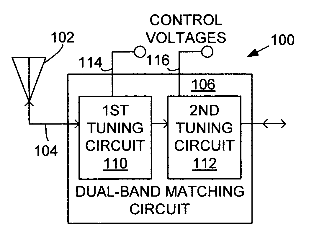
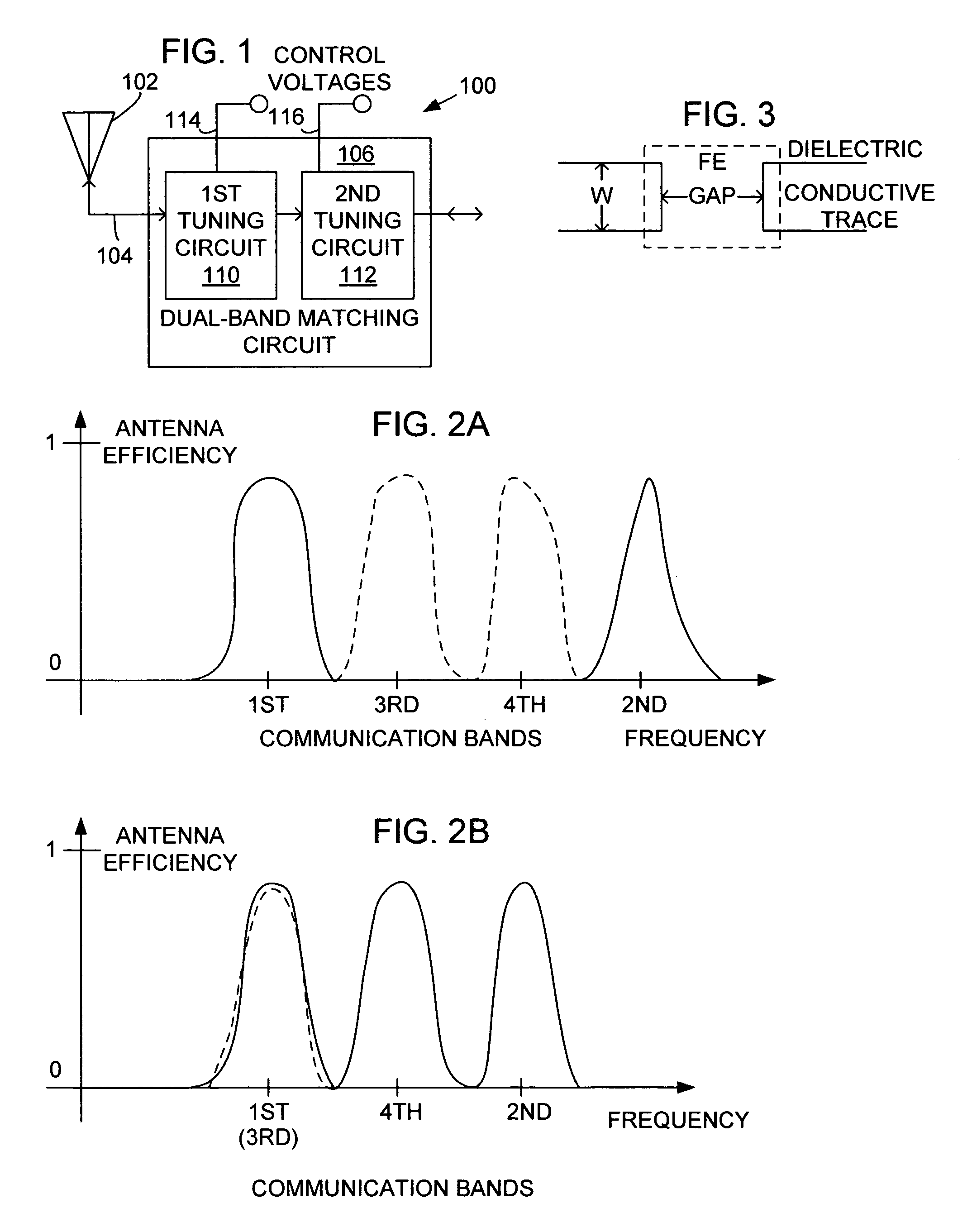
[0037]FIG. 1 is a schematic block diagram of the present invention dual-band antenna matching system. The system 100 comprises an antenna 102 having an interface port on line 104 with a frequency-dependent impedance. A dual-band matching circuit 106 includes an output port connected to the antenna interface port on line 104. Line 104 can be a transmission line, for example. The dual-band matching circuit 106 selectively supplies a conjugate impedance at a first and a second communication band. Alternately, the dual-band matching circuit 106 supplies a conjugate match at a third and a fourth communication band. Typically, the antenna has a fixed impedance that varies with respect to frequency or communication band. However, in one aspect of the system, the antenna can be frequency tunable to further the dual-band matching process.
[0038]Specifically, the dual-band matching circuit 106 supplies a conjugate impedance at the first communication band in response to a first tuned frequency...
PUM
Abstract
A dual-band antenna matching system and a method for dual-band impedance matching are provided. The method comprises: accepting a frequency-dependent impedance from an antenna; and, selectively supplying a conjugate impedance match for the antenna at either a first and a second communication band, or a third and a fourth communication band. More specifically, the method comprises: tuning a first tuning circuit to a first frequency; and, simultaneously tuning a second tuning circuit to a second frequency. In response, a conjugate match is supplied to the antenna in the first communication band in response to the first frequency. Simultaneously, the antenna is matched in the second communication band in response to the second frequency. When the first tuning circuit is tuned to a third frequency, and the second tuning circuit is tuned to a fourth frequency, then conjugate matches are supplied for the third and fourth communication bands, responsive to the third and fourth frequencies, respectively.
Description
RELATED APPLICATIONS[0001]This application is related to and is a continuation-in-part of U.S. applications “FERROELECTRIC ANTENNA AND METHOD FOR TUNING SAME”, Ser. No. 10 / 117,628, filed on Apr. 4, 2002 now U.S. Pat. No. 6,861,985; “INVERTED-F FERROELECTRIC ANTENNA”, Ser. No. 10 / 120,603, filed on Apr. 9, 2002 now U.S. Pat. No. 6,885,341; and “TUNABLE ANTENNA MATCHING CIRCUIT”, Ser. No. 10 / 075,896, filed on Feb. 12, 2002, now U.S. Pat. No. 6,765,540, all of which are incorporated herein by reference.[0002]This application is related to U.S. APPLICATIONS “TUNABLE HORN ATENNA”, Ser. No. 10 / 122,399, filed on Apr. 12, 2002 now U.S. Pat. No. 6,867,744; “TUNABLE WAVEGUIDE ATENNA”, Ser. No. 10 / 122,968, filed on Apr. 11, 2002 now U.S. Pat. No. 6,741,217; “TUNABLE DIPOLE ANTENNA”, Ser. No. 10 / 121,773, filed on Apr. 11, 2002 now U.S. Pat. No. 6,741,211; and “TUNABLE MATCHING CIRCUIT”, Ser. No. 09 / 927,136, filed on Aug. 10, 2001, all of which are incorporated herein by reference.[0003]This appl...
Claims
Application Information
Patent Timeline
Application Date:The date an application was filed.
Publication Date:The date a patent or application was officially published.
First Publication Date:The earliest publication date of a patent with the same application number.
Issue Date:Publication date of the patent grant document.
PCT Entry Date:The Entry date of PCT National Phase.
Estimated Expiry Date:The statutory expiry date of a patent right according to the Patent Law, and it is the longest term of protection that the patent right can achieve without the termination of the patent right due to other reasons(Term extension factor has been taken into account ).
Invalid Date:Actual expiry date is based on effective date or publication date of legal transaction data of invalid patent.