Visual display testing, optimization and harmonization method and system

a visual display and optimization technology, applied in the field of automatic testing, optimization and harmonization of the performance measurement of visual displays, can solve the problems of flicker increasing the likelihood of electroplating, the charge present at a subpixel tft to differ in an undetermined way from the applied voltage, etc., to achieve the effect of enhancing the value of a certain display characteristic and uniform luminan

Inactive Publication Date: 2007-02-20
AMERICAN PANEL CORP INC
View PDF23 Cites 12 Cited by
  • Summary
  • Abstract
  • Description
  • Claims
  • Application Information

AI Technical Summary

Benefits of technology

[0003]This invention relates generally to the automated testing, optimization and harmonization of the performance measurements of visual displays. Currently, systems are available to automatically test visual displays by providing measurements on display characteristics (for example: luminance, transmission level, contrast ratio, luminance uniformity, chromaticity uniformity, viewing angle dependence, and luminous efficiency) of the visual displays. Current systems may be capable of measuring, gathering and comparing the display characteristics. Some even enhance the value of a certain display characteristics, such as luminance uniformity, to the detriment of other characteristics, such as contrast ratio. They do not, however, automatically provide for the optimization of all display characteristics as may be done by the present invention. The present invention may be used with any standard automated or non-automated system for testing digital flat panel displays. One such automated system for measuring the optical performance of a visual display under test is the method described in U.S. Pat. No. 6,177,955 (which is hereby incorporated by reference in its entirety) and is embodied in the Display Tuning System manufactured by Westar Corporation located in St. Louis, Mo.
[0008]With respect to the alternating voltage potentials applied to the subpixel TFT's, if the magnitude of the positive and negative potentials at the subpixels relative to Vcom are different the light transmission level will appear to flicker as the panel refreshes. This flickering occurs because the liquid crystal switches from one orientation to the opposite depending on the polarity of the potential, and the magnitude of light transmission is determined by the magnitude of that potential. If the magnitude of the positive potential differs from the magnitude of the negative potential, the light transmission changes as the waveform changes from positive to negative, and vice versa. This “unbalanced” state resulting in flicker increases the likelihood of electroplating since a nonzero voltage potential is effectively maintained across the cell gap. “Harmonizing” an LCD display implies balancing, or correcting, this unbalanced state.
[0009]By electrically balancing, or harmonizing, a panel to a high degree of accuracy, the present invention prevents image retention, as described above, and allows for the setting of the optimum, or maximum, voltage potential range, resulting in, among other characteristics, maximum contrast ratio and maximum luminance, or light transmission level. Monotonicity is maintained and flicker is minimized. Through automation, the present invention provides for a time-efficient and highly repeatable method of harmonizing panels by generating voltage setting correction factors and storing them into memory that is incorporated into the display panel. The harmonization optimizes the panel's viewing characteristics irrespective of viewing angle.

Problems solved by technology

TFT electrical distortion and threshold offsets, among other factors, cause the charge present at a subpixel TFT to differ in an undetermined way from the applied voltage.
This “unbalanced” state resulting in flicker increases the likelihood of electroplating since a nonzero voltage potential is effectively maintained across the cell gap.

Method used


Image

  • Visual display testing, optimization and harmonization method and system
  • Visual display testing, optimization and harmonization method and system
  • Visual display testing, optimization and harmonization method and system

Examples


Embodiment Construction

)

[0022]In accordance with the foregoing summary, the following presents a detailed description of the exemplary embodiments of the invention that is currently considered to be the best mode.

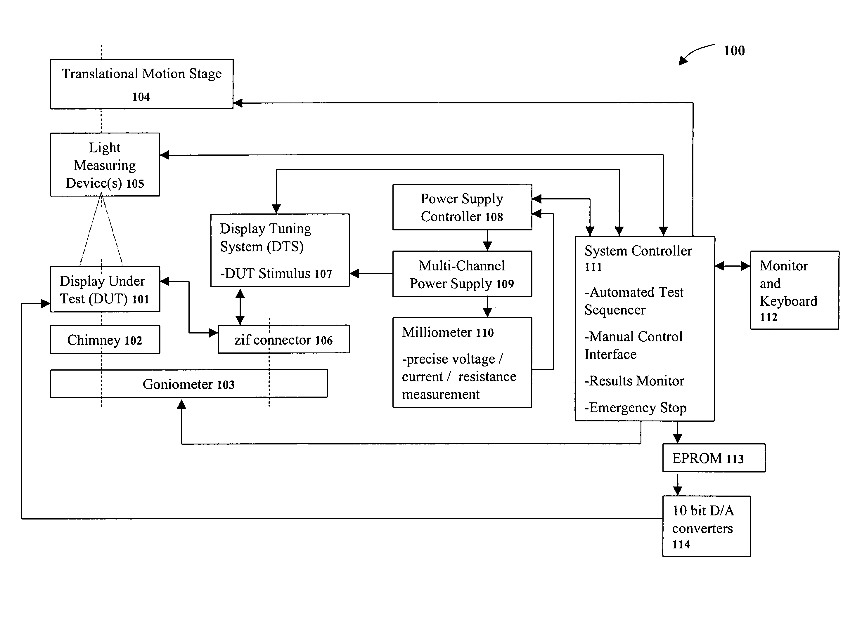
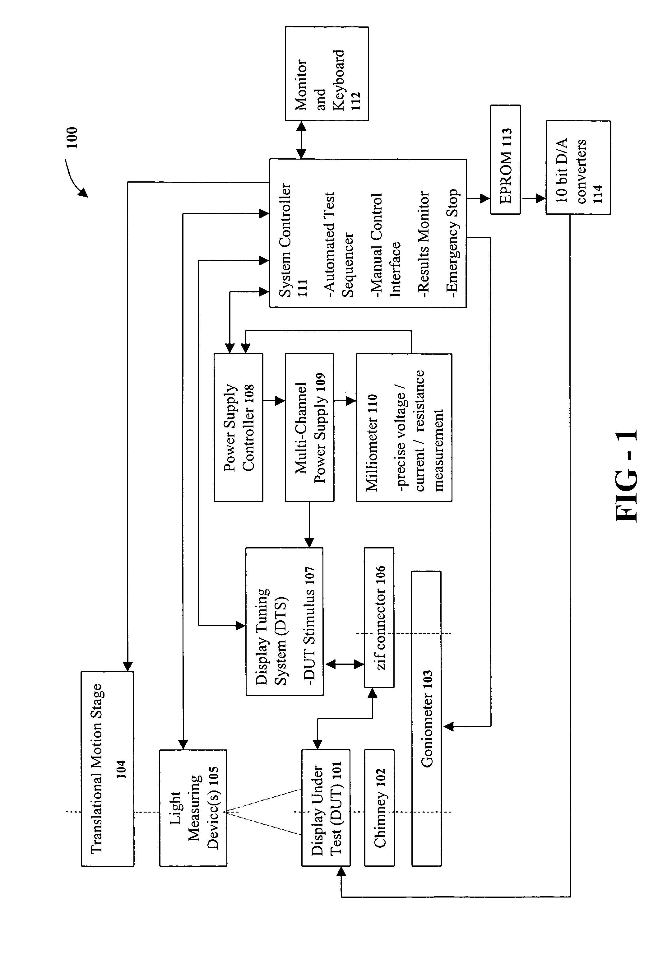
[0023]FIG. 1 is a block diagram of visual display testing and harmonization system 100 arranged in accordance with the invention to: a) subject the display under test (DUT) to a standard battery of testing procedures and measure the display's performance for success or failure and; b) conduct and implement the optimization process of the present invention.

[0024]In FIG. 1, DUT 101 is attached to a “chimney” apparatus 102 which is itself attached to goniometer 103. The chimney apparatus may generally be a square tube frame with a backlight on one end to illuminate the DUT that is attached to the other end. The four sides, being opaque, substantially prevent light from diffusing into the testing area and serve to set the DUT at a distance from the backlight.

[0025]The goniometer 103, or rotational st...


PUM

PropertyMeasurementUnit
voltagesaaaaaaaaaa
gamma voltagesaaaaaaaaaa
voltageaaaaaaaaaa

Abstract

A method and system for automatically testing visual displays and automatically optimizing the voltage settings for each visual display being tested by harmonizing and tailoring the voltage settings applied to the display and automatically setting into memory the coefficients to achieve the optimized voltage levels for each visual display.

Description

CROSS-REFERENCE TO RELATED APPLICATION[0001]This application is a continuation of U.S. application Ser. No. 10 / 244,577, filed Sep. 16, 2002, now U.S. Pat. No. 6,809,746, which is claims the benefit of Provisional Application No. 60 / 322,086, filed Sep. 14, 2001 incorporated herein by reference.[0002]The present application claims priority from and hereby incorporates by reference the substance of Provisional Application No. 60 / 322,086, filed Sep. 14, 2001.BACKGROUND AND SUMMARY OF THE INVENTION[0003]This invention relates generally to the automated testing, optimization and harmonization of the performance measurements of visual displays. Currently, systems are available to automatically test visual displays by providing measurements on display characteristics (for example: luminance, transmission level, contrast ratio, luminance uniformity, chromaticity uniformity, viewing angle dependence, and luminous efficiency) of the visual displays. Current systems may be capable of measuring,...

Claims


Application Information

Patent Timeline
Patent Type & Authority Patents(United States)
IPC IPC(8): G09G5/10G02F1/13G01M11/00G01M99/00G02F1/133G09G3/20G09G3/36
CPCG09G3/006G09G3/3655H04N17/04Y10S345/904G09G2320/0276G09G2320/0247G09G3/36H04N17/02H04N17/00G01R31/28
Inventor WHITTINGTON, AMYDUNN, WILLIAM
Owner AMERICAN PANEL CORP INC
Why Eureka
Try Eureka