
Wired endian method and apparatus for performing the same

a wired endian and method technology, applied in the field of electronic device communication, can solve the problems of inefficient duplication of essentially equivalent circuitry components and associated code sets, and it is difficult to efficiently define a device that is capable,

Inactive Publication Date: 2007-02-20
PMC-SIERRA
View PDF5 Cites 20 Cited by
  • Summary
  • Abstract
  • Description
  • Claims
  • Application Information

AI Technical Summary

Benefits of technology

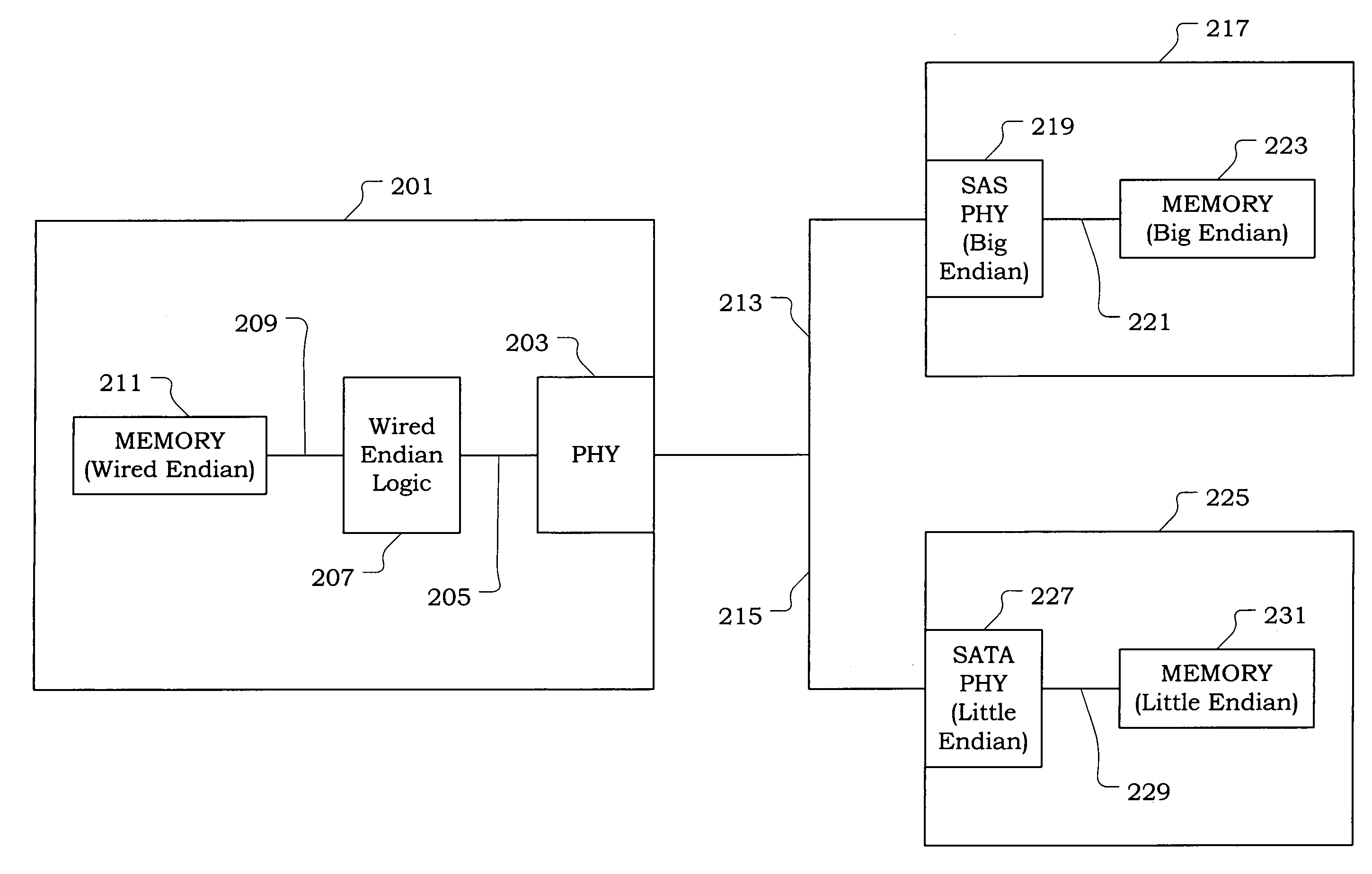
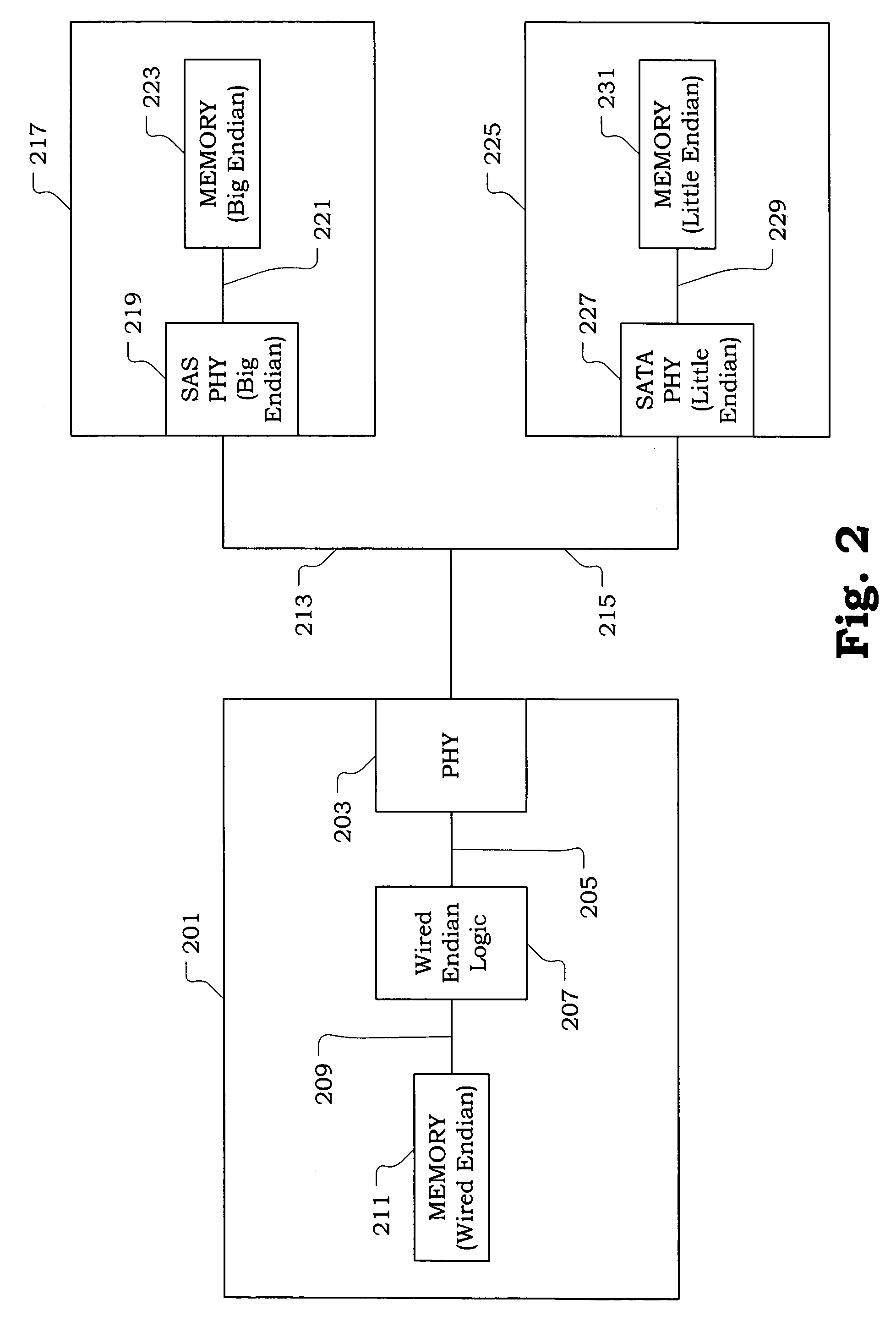
[0010]The present invention provides a method and associated apparatus for operating an electronic device in accordance with a wired endian format. More specifically, the wired endian format requires multi-byte values be maintained in transmit order. The wired endian format is defined to allow for interfacing with both a big endian format and a little endian format. Thus, a device operating in accordance with the wired endian format as described herein is able to interface with both a device operating in accordance with the big endian format (e.g., a Serial Attached SCSI (SAS) device) and a device operating in accordance with the little endian format (e.g., a Serial ATA (SATA) device). Furthermore, since the device operating in accordance with wired endian format implements circuitry compliant with the wired endian format, duplication of circuitry to define separate data paths for interfacing with the big endian and little endian formats, respectively, is avoided.

Problems solved by technology

Thus, it is difficult to efficiently define a device that is capable of interfacing and operating with both the big endian and the little endian formats.
Thus, the conventional approach has suffered from inefficient duplication of essentially equivalent circuitry components and associated code sets to support each of the independent data paths.

Method used


Image

  • Wired endian method and apparatus for performing the same
  • Wired endian method and apparatus for performing the same
  • Wired endian method and apparatus for performing the same

Examples


Embodiment Construction

[0022]The present invention provides a method and associated apparatus for operating an electronic device in accordance with a wired endian format. More specifically, the wired endian format requires multi-byte values be maintained in transmit order. The wired endian format is defined to allow for interfacing with both a big endian format and a little endian format. Thus, a device operating in accordance with the wired endian format as described herein is able to interface with both a device operating in accordance with the big endian format (e.g., a SAS device) and a device operating in accordance with the little endian format (e.g., a SATA device). Furthermore, since the device operating in accordance with wired endian format implements circuitry compliant with the wired endian format, duplication of circuitry to define separate data paths for interfacing with the big endian and little endian formats, respectively, is avoided.

[0023]It should be appreciated that the present inventi...


PUM


Abstract

A method and associated apparatus is provided for operating an electronic device in accordance with a wired endian format. More specifically, the wired endian format requires multi-byte values be maintained in transmit order. The wired endian format is defined to allow for interfacing with both a big endian format and a little endian format. Thus, a device operating in accordance with the wired endian format is able to interface with both a device operating in accordance with the big endian format (e.g., a Serial Attached SCSI (SAS) device) and a device operating in accordance with the little endian format (e.g., a Serial ATA (SATA) device). Furthermore, since the device operating in accordance with wired endian format implements circuitry compliant with the wired endian format, duplication of circuitry to define separate data paths for interfacing with the big endian and little endian formats, respectively, is avoided.

Description

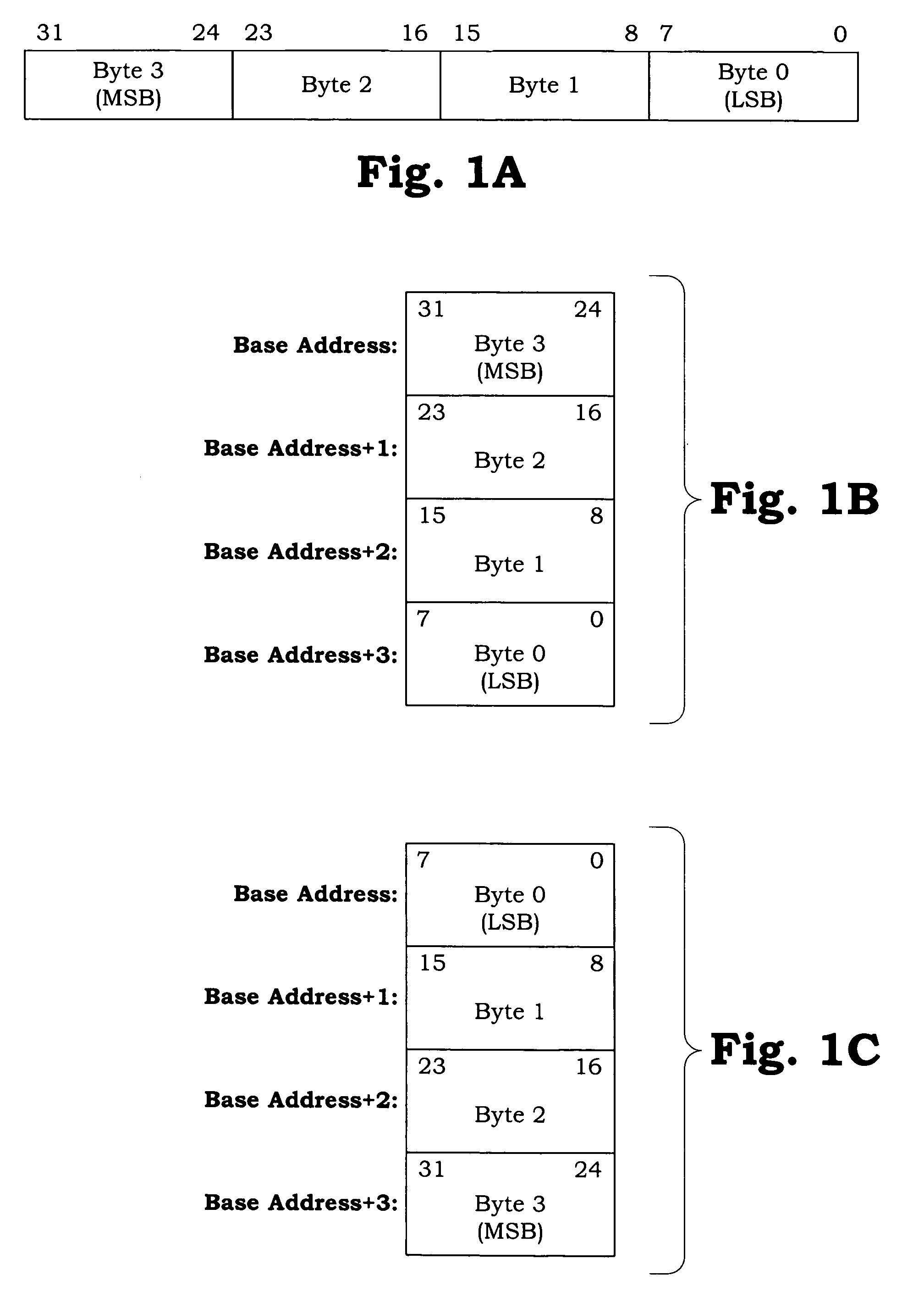
BACKGROUND[0001]1. Field of the Invention[0002]The present invention relates generally electronic device communication.[0003]2. Description of the Related Art[0004]In modern computing systems, multi-byte values are conventionally stored in either a big endian format or a little endian format. Also, it is generally required that a particular format be applied consistently to ensure compatibility between various components of the computing system. The big endian and little endian formats and the necessity for their consistent application is described below with respect to FIGS. 1A through 1C.[0005]FIG. 1A is an illustration showing an exemplary sequence of bytes to be used as a basis for describing a big endian format and a little endian format. Byte 0 includes bits 0 through 7. Byte 1 includes bits 8 through 15. Byte 2 includes bits 16 through 23. Byte 3 includes bits 24 through 31. For discussion purposes, Byte 3 is defined to be the most significant byte (MSB), and Byte 0 is define...

Claims


Application Information

Patent Timeline
IPC IPC(8): G06F13/36G06F13/00G06F7/38G06F13/12
CPCG06F13/4013G06F3/0661G06F3/0674
Inventor STENFORT, ROSSPACKER, JOHN
Owner PMC-SIERRA
Learn More