Cooling fan system for automotive vehicle

Inactive Publication Date: 2007-02-27
FORD GLOBAL TECH LLC
View PDF10 Cites 22 Cited by
  • Summary
  • Abstract
  • Description
  • Claims
  • Application Information

AI Technical Summary

Benefits of technology

[0010]It is an advantage of a cooling system according to the present invention that increased engine cooling may be achieved without expending the additional energy required to power a cooling fan.
[00

Problems solved by technology

This type of fan architecture suffers from one major drawback.
Namely, in the event that the vehicle is being operated at a high, or even moderate, ground speed, such that ram air entering the vehicle at the front of the radiator would develop a sufficient pressure to force ambient air through the radiator, the fan blades and hub severely block the airflow.
Although some fans are clutched with a thermostatic

Method used


Image

  • Cooling fan system for automotive vehicle
  • Cooling fan system for automotive vehicle
  • Cooling fan system for automotive vehicle

Examples


Example

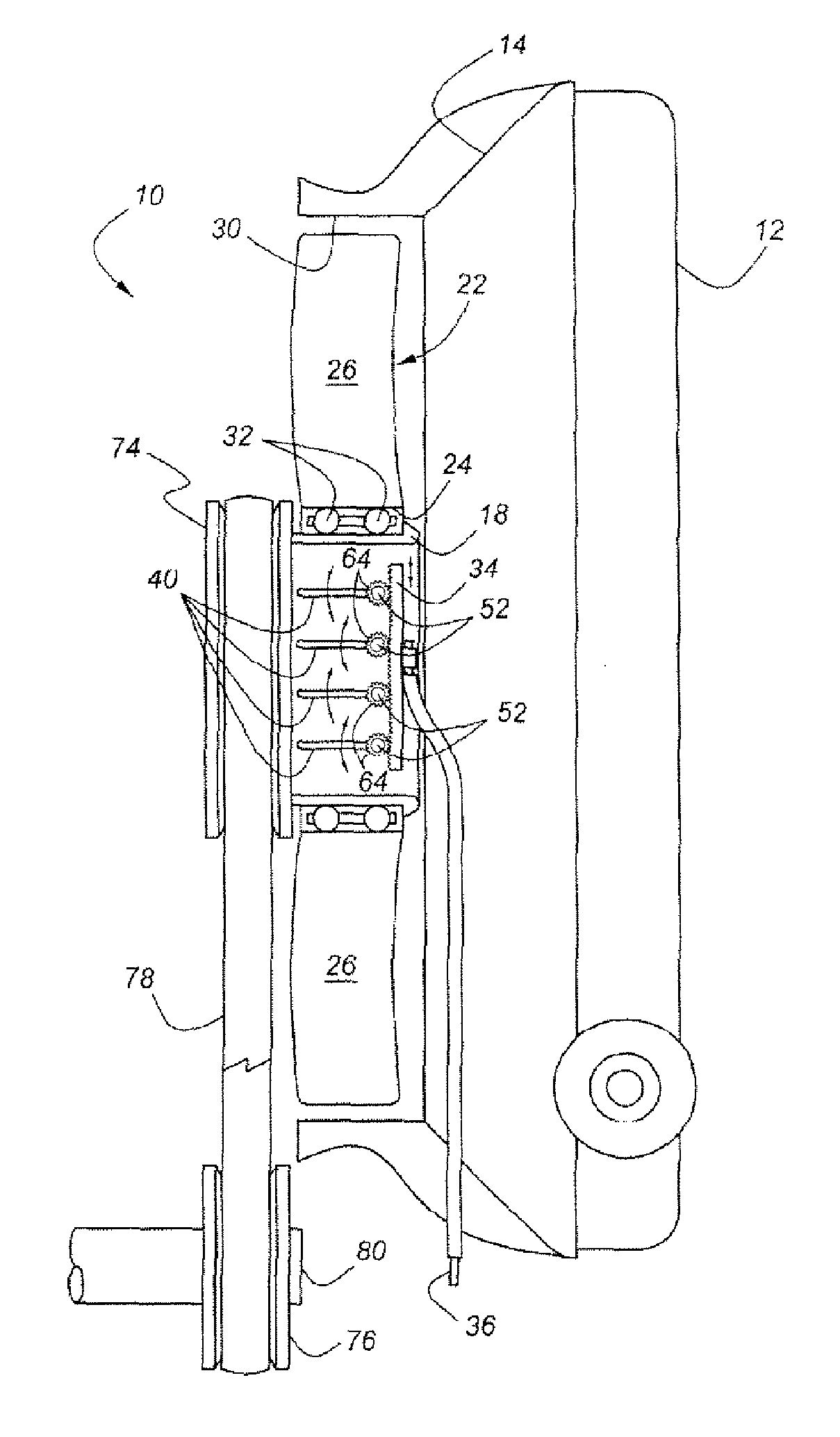
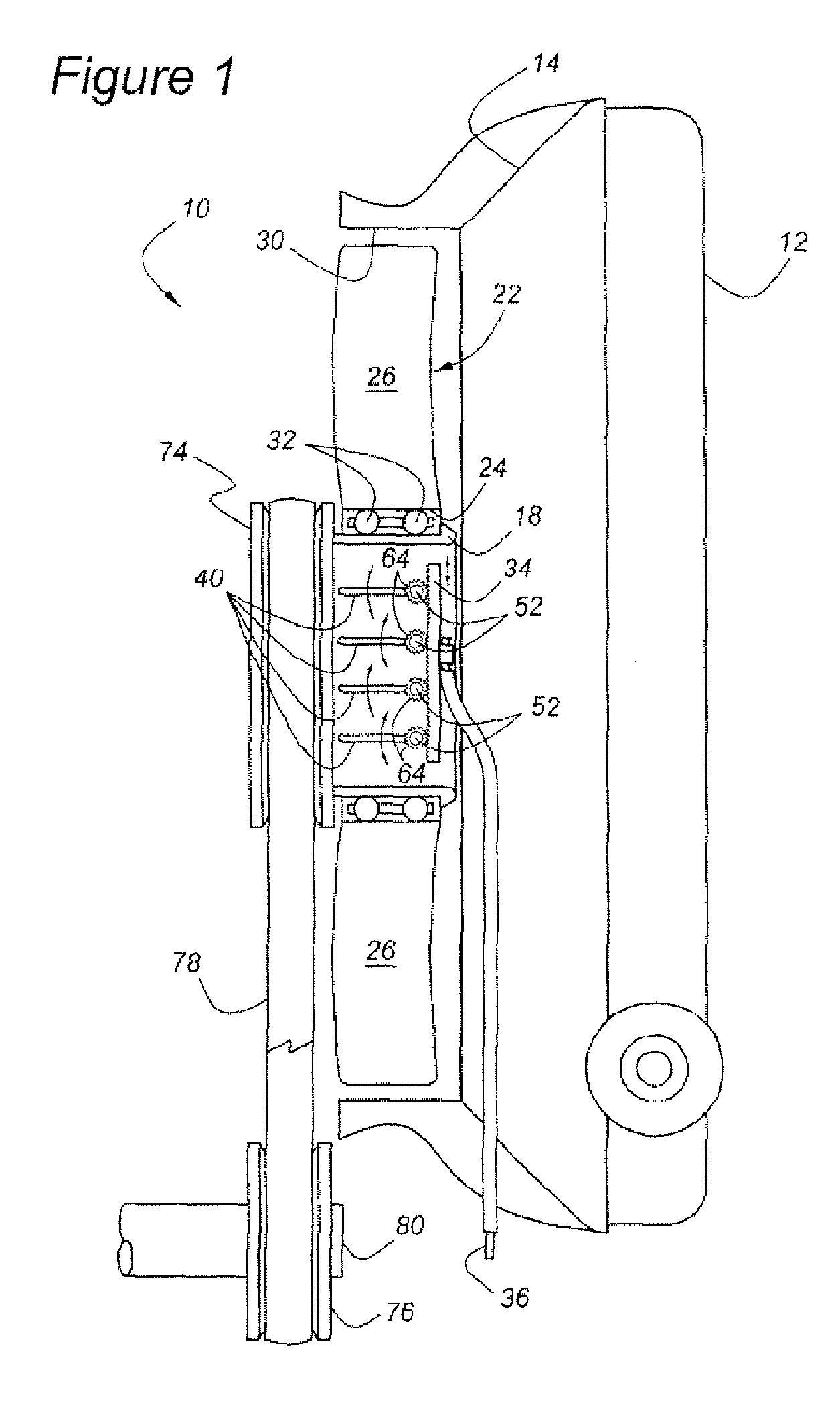
[0018]As shown in FIG. 1, cooling system 10 includes radiator 12, having fan shroud 14 mounted thereto. An axial flow fan element, 22, is mounted within a circular aperture, 30, formed in fan shroud 14. Fan element 22 has a number of fan blades, 26, which are mounted to circular bearing surface 24, which is an annular structure upon which each of the fan blades 26 is mounted. Bearing surface 24 defines the inner periphery of fan element 22. Bearing surface 24 and fan element 22 are journaled by means of bearings 32 to hub 18, which is stationary. Hub 18 may be mounted upon fan shroud 14, or upon another stationary engine part or vehicle part. What is important is that hub 18 does not rotate. Rather, fan element 22 rotates upon hub 18. This rotation is powered by means of sheave 74, belt 78 and sheave 76, which may be mounted to either a rotating engine shaft, such as crankshaft 80, or to a fan motor 112 (FIG. 4). Belt 78 thus serves as a flexible power transmission member trained ab...


PUM


Abstract

A cooling system for an internal combustion engine mounted within a vehicle includes a radiator for rejecting heat to ambient air and an axial fan mounted within a fan shroud associated with a radiator. The fan has a stationary hub equipped with louvers which may be controlled so as to either block off or allow airflow through the hub, and consequentially through the radiator. In this manner, the airflow past the fan may be greatly increased when the vehicle is operated at a higher groundspeed, while decreasing the amount of power consumed by the fan.

Description

BACKGROUND OF THE INVENTION[0001]The present invention relates to a fan system for drawing ambient air through the radiator of an internal combustion engine cooling system.[0002]Both engine-driven and hydraulic or electrically-driven radiator cooling fans have been used for almost a century with internal combustion engines. Such cooling fans typically include a multi-bladed element mounted upon a centrally located motor. U.S. Pat. No. 5,660,149 and U.S. Pat. No. 6,342,741, as well Published Application No. U.S. 2004 / 0223845 all disclose typical radiator cooling fans in which the motor is mounted at the center of the fan arrangement. This type of fan architecture suffers from one major drawback. Namely, in the event that the vehicle is being operated at a high, or even moderate, ground speed, such that ram air entering the vehicle at the front of the radiator would develop a sufficient pressure to force ambient air through the radiator, the fan blades and hub severely block the airfl...

Claims


Application Information

Patent Timeline
IPC IPC(8): F01P7/02F01P7/10
CPCF01P5/06F04D29/582F04D29/329F01P7/10F04D27/003F04D29/059F04D29/563
Inventor SCHWARTZ, WILLIAM
Owner FORD GLOBAL TECH LLC
Why Eureka
Try Eureka