Integrated aircraft structural floor

a technology for aircraft and structural floors, applied in the field of aircraft structural floors, can solve the problems of unmatched structural support and excessive lightness of honeycomb structures

Active Publication Date: 2007-02-27
THE BOEING CO
View PDF25 Cites 42 Cited by
  • Summary
  • Abstract
  • Description
  • Claims
  • Application Information

AI Technical Summary

Benefits of technology

[0042]The many features and advantages of the invention are apparent from the detailed specification, and thus, it is intended by the appended claims to cover all such features and advantages of the invention which fall within the true spirit and scope of the invention. Further, since numerous modifications and variations will readily occur to those skilled in the art, it is not desired to limit the invention to the exact construction and operation illustrated and described, and accordingly, all suitable modifications and equivalents may be resorted to, falling within the scope of the invention.

Problems solved by technology

Honeycomb structures are exceeding light materials that provide unequalled structural support (for their weight) when placed in wings and other strategic locations in a given aircraft.

Method used


Image

  • Integrated aircraft structural floor
  • Integrated aircraft structural floor
  • Integrated aircraft structural floor

Examples


Embodiment Construction

[0021]The disclosed composite floors represent a variety of inventive innovations created to provide modern aircraft with rugged, yet exceedingly light structural components.

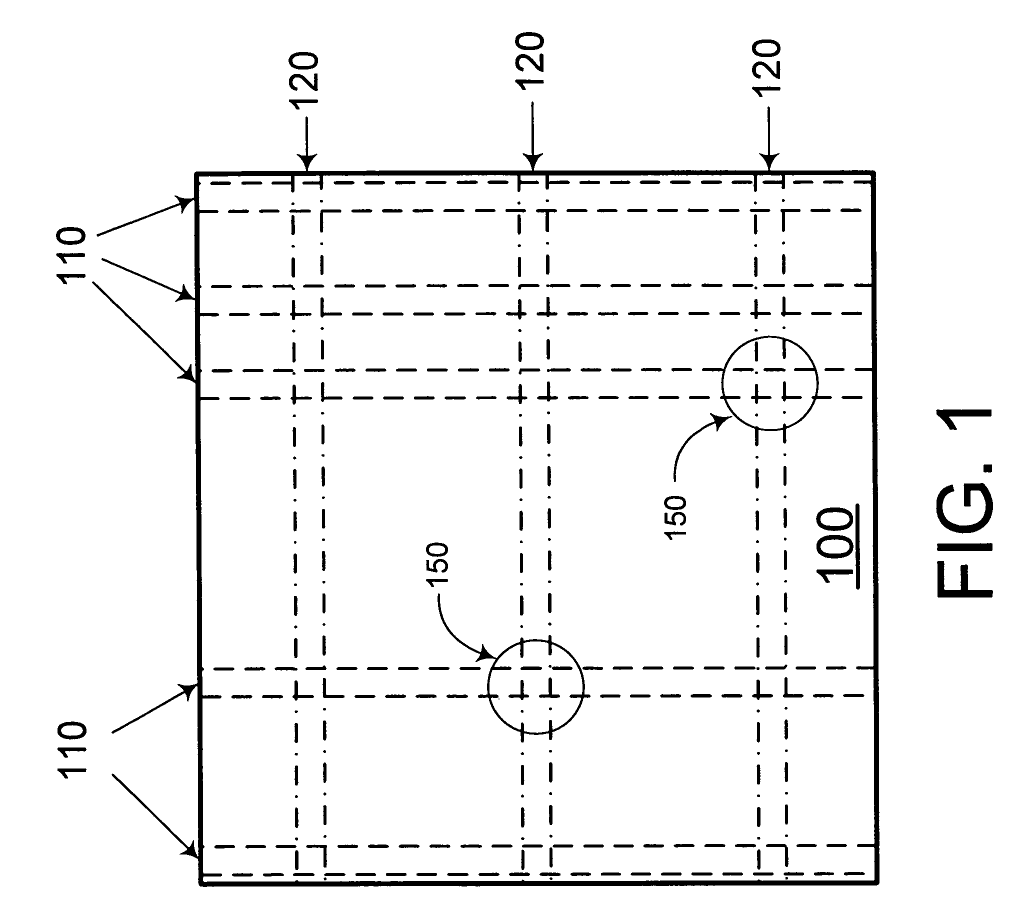
[0022]FIG. 1 is a top view of a portion of an exemplary composite floor 100. As shown in FIG. 1, the composite floor portion 100 includes a number of seating tracks 110 running along the length of the composite floor portion 100 as well as a number of floor beam paths 120 running along the width of the composite floor portion 100. As further shown in FIG. 1, the seating tracks 110 and beam paths 120 generally run perpendicular to each other, and a number of intersection nodes 150 are found wherever a particular seating track 110 crosses a particular beam path 120.

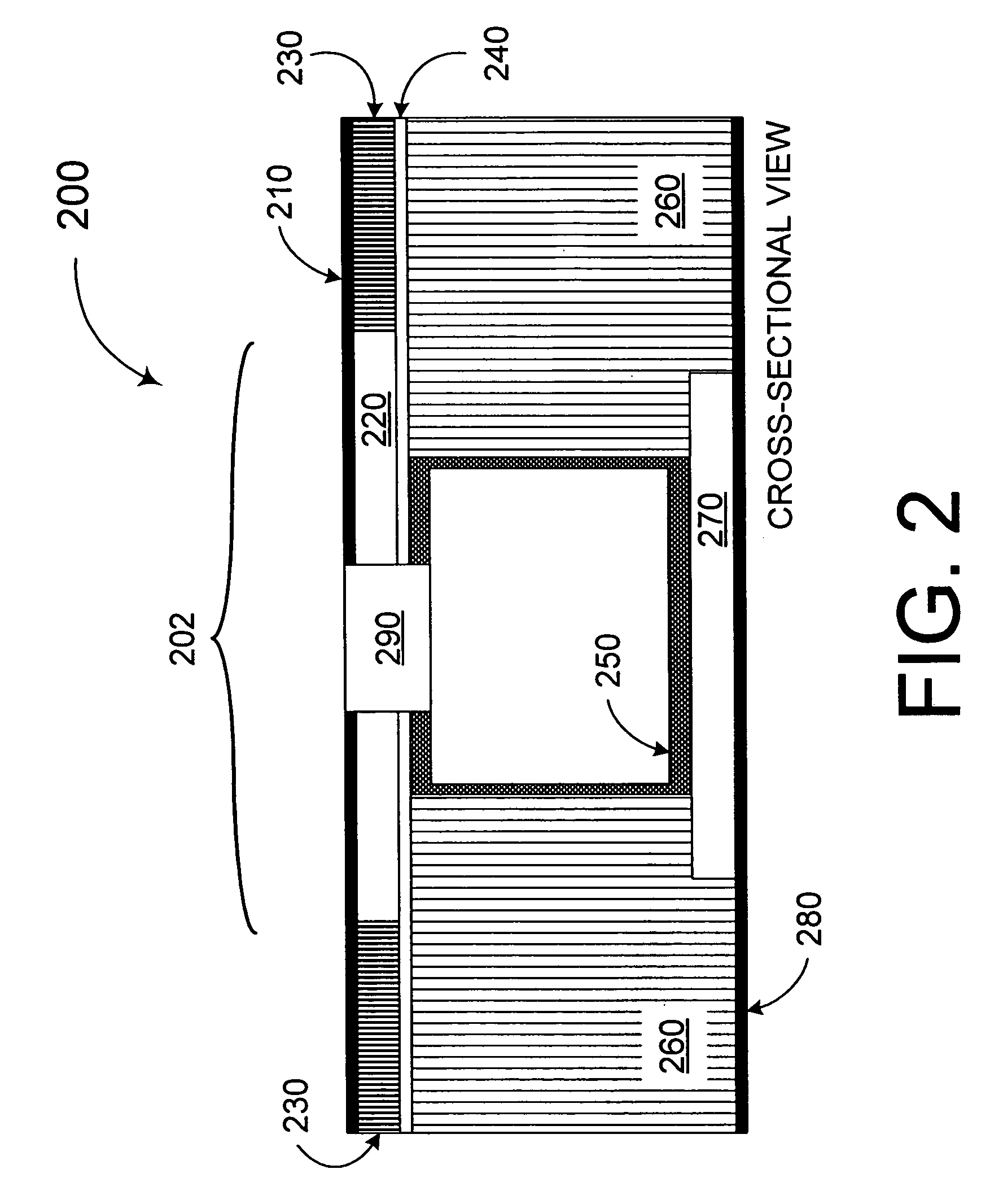
[0023]FIG. 2 depicts a cross-sectional view of a portion of a first exemplary composite floor 200. As shown in FIG. 2, first exemplary composite floor portion 200 has a top-layer skin 210 (a skin being a type of covering, or skin), a high-density core 2...


PUM


Abstract

A number of integrated floor structures made of lightweight composite materials for use in an aircraft are disclosed. Generally, each of such floors includes a top-layer skin, a bottom-layer skin disposed below the top-layer skin and a first structural core disposed between the top-layer skin and the bottom-layer skin, the first structural core being composed of a honeycomb composite material. One or more denser structural cores can also be incorporated at strategic locations.

Description

FIELD OF THE INVENTION[0001]This invention relates to novel structures and devices for lightweight aircraft floors.BACKGROUND OF THE INVENTION[0002]Originally, naturally available and relatively light materials, such as wood, were the most common materials used for constructing aircraft. However, with the development of new alloys the aircraft construction industry shifted from one of carpentry to one of metal shaping.[0003]Relatively recently, a new generation of materials known as “composites” or “composite materials” were developed. Certain composite materials often provide an excellent strength-to-weight ratio as compared to metals, and their acceptance into the various aircraft industries is near universal.[0004]Generally, there are two major genres of composite materials: honeycomb structures and laminates. Honeycomb structures are exceeding light materials that provide unequalled structural support (for their weight) when placed in wings and other strategic locations in a giv...

Claims


Application Information

Patent Timeline
Patent Type & Authority Patents(United States)
IPC IPC(8): B64C1/18
CPCB64C1/18B61D17/10Y02T50/40
Inventor WESTRE, WILLIARD N.EVANS, DAVID W.
Owner THE BOEING CO
Why Eureka
Try Eureka