
Joining structure

a jointing structure and jointing technology, applied in the direction of non-disconnectible pipe joints, manufacturing tools, rod connections, etc., can solve the problems of reducing structural performance, reducing and reducing structural performance, so as to improve the proof stress and fatigue performance of the joining structure. , the effect of low rigidity structur

Active Publication Date: 2007-02-27
NIPPON STEEL CORP
View PDF15 Cites 8 Cited by
  • Summary
  • Abstract
  • Description
  • Claims
  • Application Information

AI Technical Summary

Benefits of technology

The present invention provides a joining structure between two columnar structural members that reduces stress concentration and residual tensing welding stress, resulting in improved proof stress and fatigue performance. The joining structure includes a reinforcing member welded to the structural members and having U- or V-shaped bent portions along the surface of the structural members. The reinforcing member may have an opening in the end surface formed by the end portion of the reinforcing member. The technical effects of this invention include reduced stress concentration and improved fatigue performance of the joining structure.

Problems solved by technology

A large stress is concentrated on the first columnar structural member 10 near to the fixed end portions 14 of the tabular reinforcing members 12, thereby likely posing a problem of a reduced structural performance.
Further, in the case where the tabular reinforcing members 12 are welded to the first columnar structural member 10, the boxing portion at the upper end portion of each tabular reinforcing member 12 may develop a structural defect due to the double effects of the residual welding stress and deterioration of the material of the thermally affected member at the welding fixed end portions, thus posing a problem of a reduced proof stress and a reduced fatigue performance.
At the joining portion between the open end 16 of each U- or V-shaped reinforcing member 13 and the second structural member 11, a large stress concentration may occurs on the second structural member 11 in the vicinity of the fixed end portions of the open ends 16 of the U- or V-shaped reinforcing members 13 when the bending moment is exerted on the first columnar structural member 10, thereby likely leading to a problem of a reduced structural performance.
Further, in the case where the open end portion 16 of each U- or V-shaped reinforcing member 13 is welded to the second structural member 11, the boxing portion of the open end of the U or V-shaped reinforcing member 13 may develop a structural defect due to the double effects of the residual welding stress and the deterioration of the material of the thermally-affected portion at the fixed end portion, thus posing the problem of a reduced proof stress and fatigue performance.

Method used


Image

  • Joining structure
  • Joining structure
  • Joining structure

Examples


example

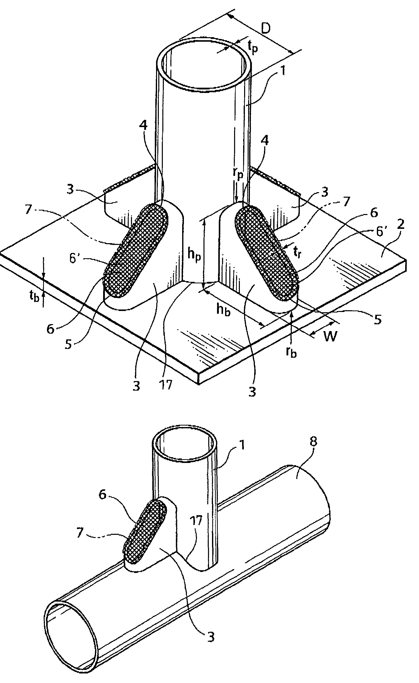
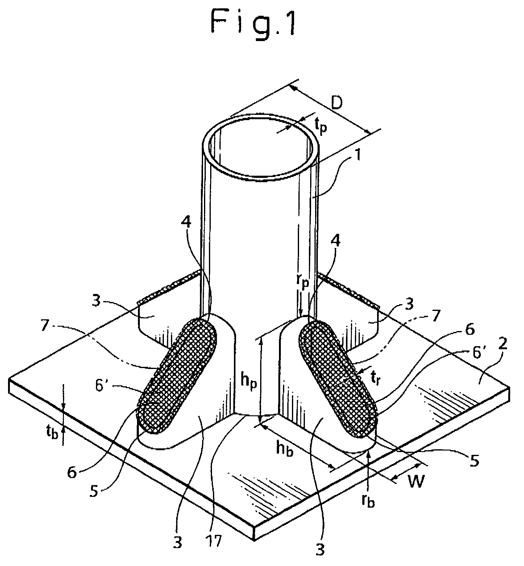
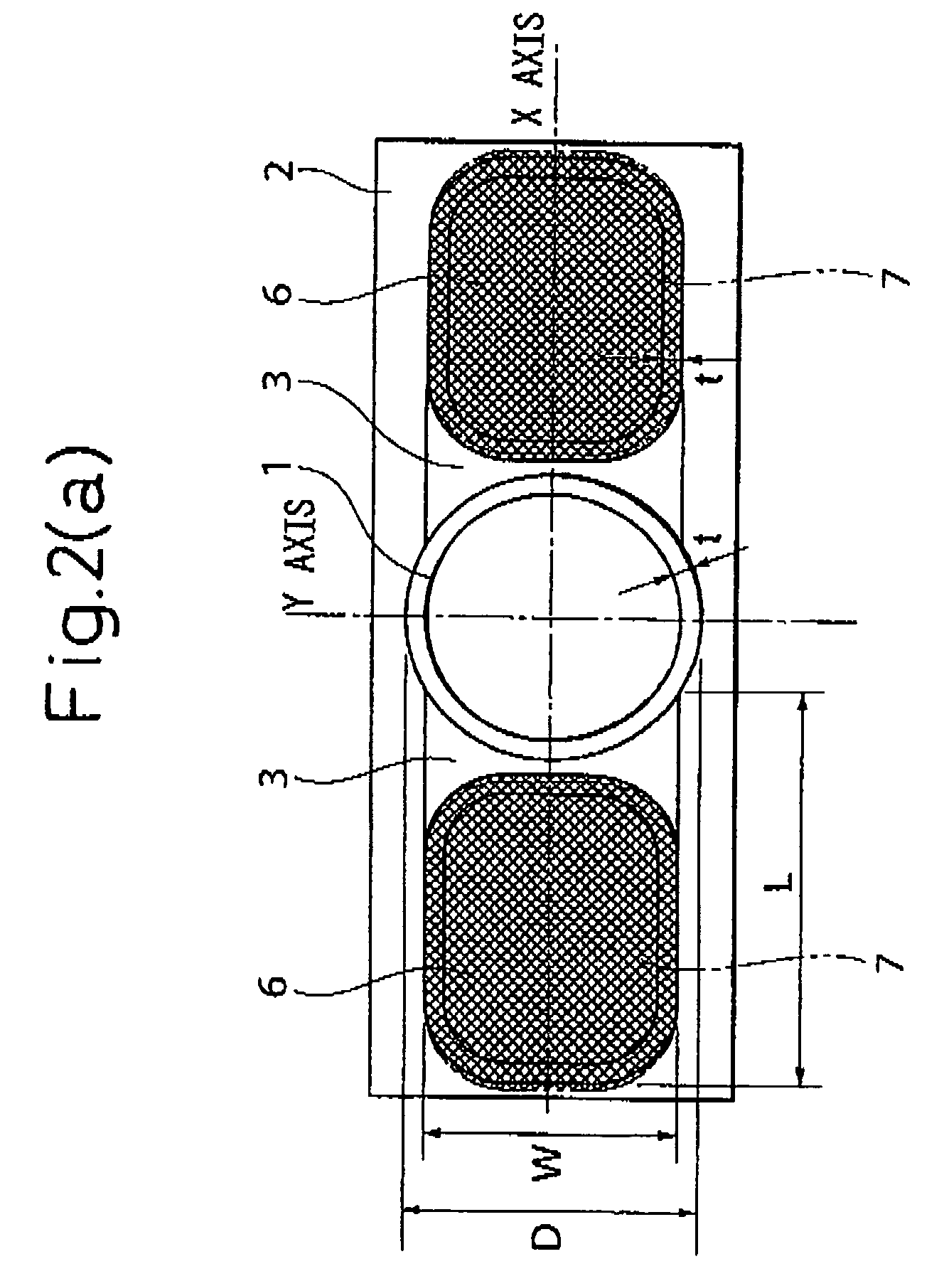
[0063]In the exemplary embodiment of the present invention shown in FIG. 1, the first columnar structural member 1 may have an outer diameter D of 163 mm, the columnar structural member 2 can have a thickness tp of 4.5 mm, the tabular structural member has a thickness tb of 25 mm, the reinforcing member may have a thickness tr of 6.0 mm, the length hp of the reinforcing member on the side of the first columnar structural member may be 200 mm, the length hb of the reinforcing member on the side of the tabular structural member may be 100 mm, the width W of the reinforcing member may be 40 mm, the radius of curvature rp of the reinforcing member on the side of the first columnar structural member (upper end portion) may be 40 mm, and the radius of curvature rb of the reinforcing member on the side of the tabular structural member (lower end portion) may be 40 mm. The result of an experiment conducted to apply the horizontal force as a load on the first columnar structural member 1 ind...


PUM


Abstract

A structure is provided between a first columnar structural member and at least a second structural member in which the stress concentration at the fixed end portion of the reinforcing member with the first columnar structural member and the second structural member(s) is greatly relaxed. Also, in the case where the reinforcing member is welded, the residual welding stress is relaxed, with the result that the proof stress and the fatigue performance are remarkably improved over the prior art. In the joining structure with the first columnar structural member and the second structural member(s), the first columnar structural member and the second structural member(s) joined to each other have welded thereto at least a tabular reinforcing member to reinforce the joining of the structural members. The reinforcing member has a U- or V-shaped bent portion along the surface of the structural members and also an opening.

Description

CROSS-REFERENCE TO RELATED APPLICATION(S)[0001]The present application claims priority under 35 U.S.C. § 119 from Japanese Patent Application No. 2003-199723, filed on Jul. 22, 2003, the entire disclosure of which is incorporated herein by reference.FIELD OF THE INVENTION[0002]The present invention relates to a joining structure, and more particularly to the joining structure that is adapted to be arranged between a first columnar structural member and a second structural member.BACKGROUND INFORMATION[0003]Conventionally, a joining structure formed as a tabular reinforcing member or a U- or V-shaped reinforcing member, may be welded between a first columnar steel structural member and second structural member (such as a first columnar structural member crossing a tabular structural member or second columnar structural member—for example, see Japanese Patent Publication Nos. 2001-132102 and 2003-001476, the entire disclosures of which are incorporated herein by reference).[0004]FIG. ...

Claims


Application Information

Patent Timeline
Patent Type & Authority Patents(United States)
IPC IPC(8): F16B7/00F16B9/00E04B1/24E04B1/58E04H12/22
CPCE04B1/2403E04H12/2261E04B1/5837E04B2001/2415Y10T403/27Y10T403/28Y10T403/477E04B2001/2451E04H12/2269E04H12/2292
Inventor KONDO, TETSUMISUGIMOTO, MASAKAZU
Owner NIPPON STEEL CORP
Learn More