Drywall rasp

a drywall and stanley® technology, applied in the field of stanley® rasps, can solve the problems of inability to cut these sheets to size, inability to smooth stanley® rasps, and inability to cut them to size,

Inactive Publication Date: 2007-02-27
MORRIS JEFFREY R
View PDF16 Cites 7 Cited by
  • Summary
  • Abstract
  • Description
  • Claims
  • Application Information

AI Technical Summary

Benefits of technology

[0022]There has thus been outlined, rather broadly, the more important features of the invention in order that the detailed description thereof that follows may be better understood, and in order that the present contribution to the art may be better appreciated. There are additional features of the invention that will be described hereinafter and which will form the subject matter of the claims appended hereto.
[0023]It is noted the purpose of the foregoing abstract is to enable the ...

Problems solved by technology

When sheets of drywall are being installed, it is often necessary to cut these sheets to size on the job.
The broken edge is invariably rough and must be smoothed prior to installation.
However, this rasp is not specifically designed for the specific task at issue and is often employed for lack of a better device.
The STANLEY® rasp is much larger than necessary for the job, is bulky and often slips off the rough cut edge of the drywall when in use.
Furthermore, the replacement blades for this tool are expensive and require the use of a screwdriver for installation and removal.
However, they are also the source of many painful injuries.
Since the expanded metal abrasive element is wrapped over the outer edges of a supporting block, there is a considerable exposure of sharp surface area that creates painful injuries with only light contact to the skin of a user.
As a conseq...

Method used


Image

  • Drywall rasp
  • Drywall rasp
  • Drywall rasp

Examples


Embodiment Construction

[0029]The present invention will now be described more fully hereinafter with reference to the accompanying drawings, in which a preferred embodiment of the invention is shown. This invention may, however, be embodied in many different forms and should not be construed as limited to the embodiment set forth herein. Rather, this embodiment is provided so that this application will be thorough and complete, and will fully convey the true scope of the invention to those skilled in the art. Like numbers refer to like elements throughout the figures.

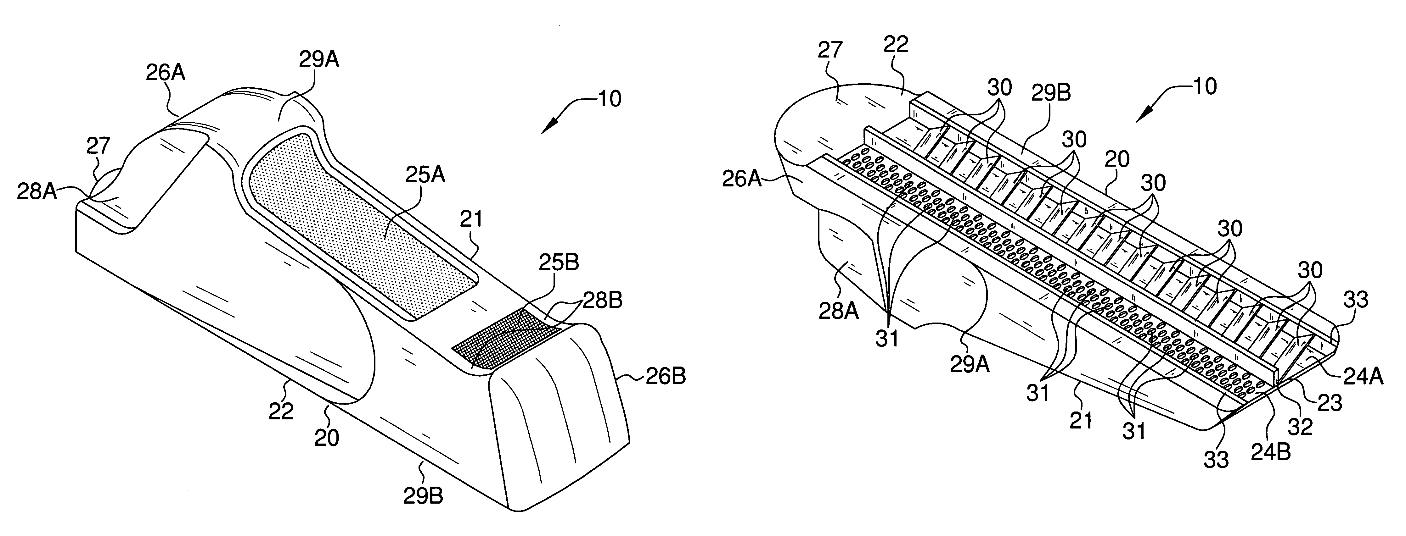
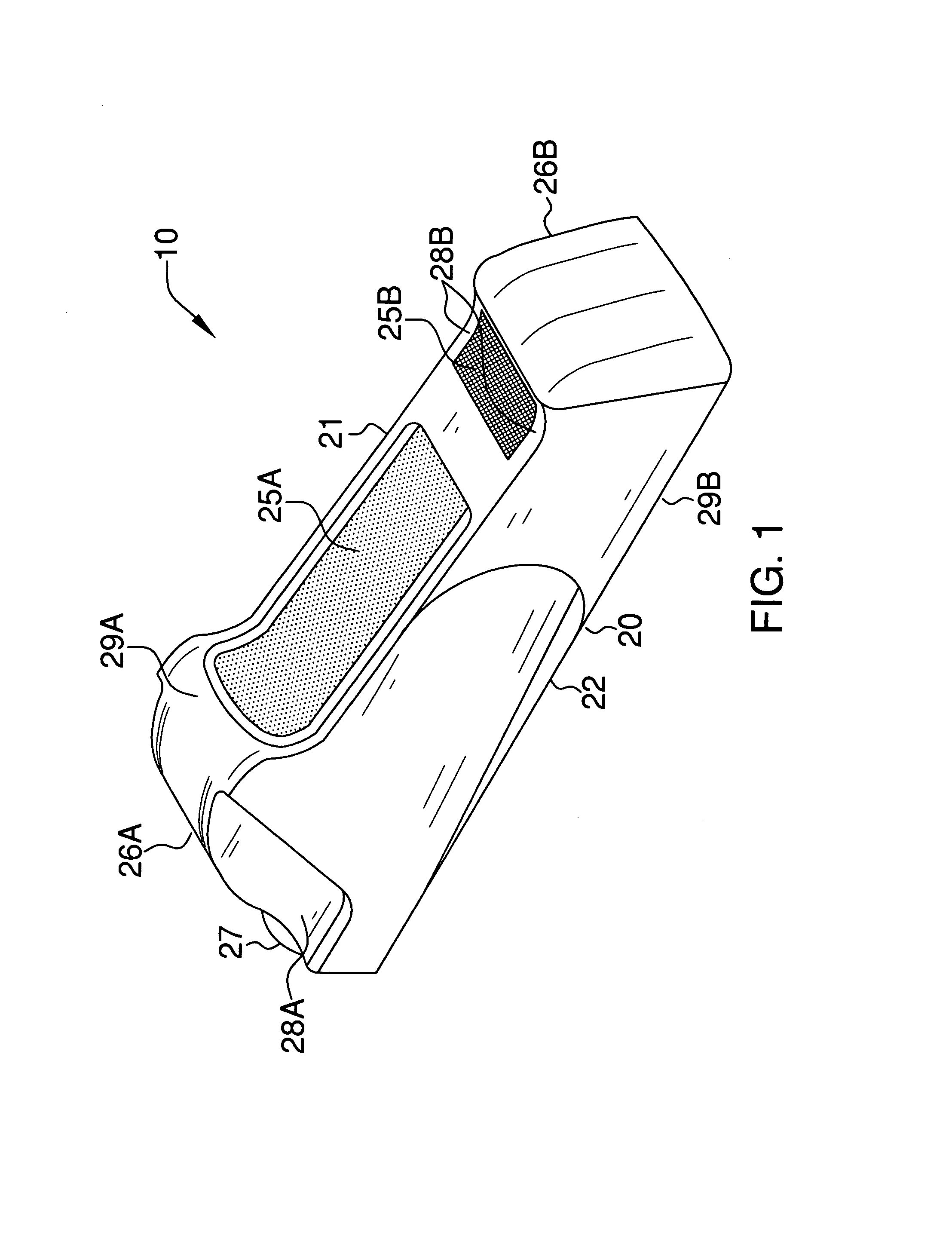
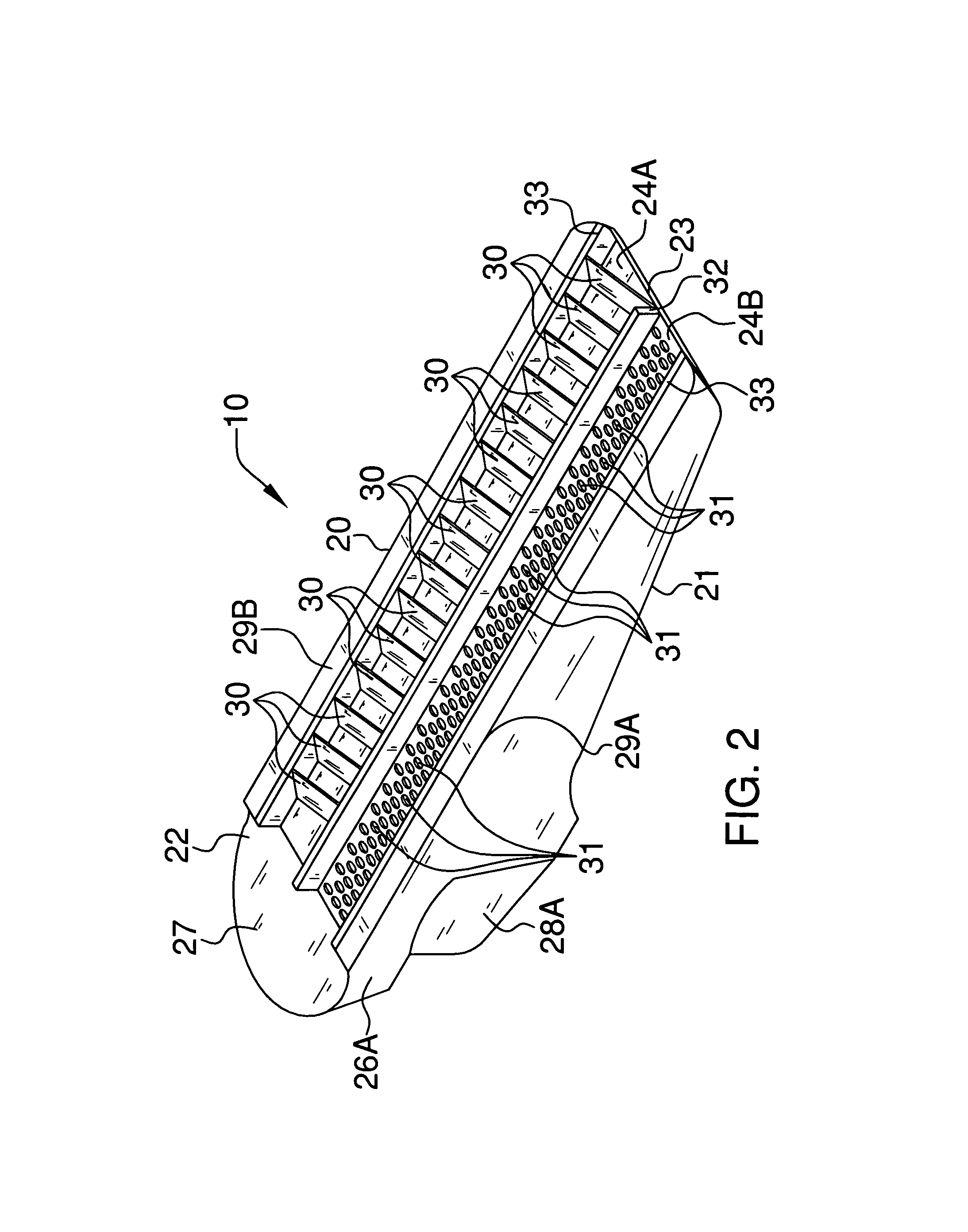
[0030]The apparatus of this invention is referred to generally in FIGS. 1–4 by the reference numeral 10 and is intended to provide a drywall rasp. It should be understood that the apparatus 10 may be used to smooth and angle many different types of sheeted material and should not be limited in use to only drywall.

[0031]Referring initially to FIGS. 1 and 2, the apparatus 10 includes a body 20 including upper 21 and lower 22 portions. Such a lo...


PUM


Abstract

A rasp includes a body including upper, lower, front and rear portions. The lower portion has a groove that has first and second sections extending along a length thereof. The first section includes equidistantly spaced coextensive cutting blades extending downwardly therefrom. The blades have front and rear surfaces that have a rectangular shape engageable along a portion of drywall. The second section includes randomly spaced protrusions that have arcuate shapes and extend downwardly therefrom. The protrusions are engageable with drywall for removing imperfections therefrom. A divider bifurcates the first and second sections and extends downwardly from the body. The divider has a height equal to that of the sidewalls. Coextensive sidewalls are conjoined with the body and oppositely spaced from the divider. The sidewalls protrude downwardly from the bottom surface and terminate coplanar with the divider. The first and second sections are recessed from the divider and the sidewalls.

Description

CROSS REFERENCE TO RELATED APPLICATIONS[0001]Not Applicable.STATEMENT REGARDING FEDERALLY SPONSORED RESEARCH OR DEVELOPMENT[0002]Not Applicable.REFERENCE TO A MICROFICHE APPENDIX[0003]Not Applicable.BACKGROUND OF THE INVENTION[0004]1. Technical Field[0005]This invention relates to rasps and, more particularly, to a drywall rasp for smoothing the edges of a drywall panel at either a 45 or 90 degree angle.[0006]2. Prior Art[0007]Drywall, also known as wallboard, is made in part from gypsum and is supplied in the form of sheets which are then mounted to walls, ceilings and other structures to present an aesthetic, smooth surface. When sheets of drywall are being installed, it is often necessary to cut these sheets to size on the job. One common method of cutting drywall involves scoring the sheet with a sharp blade or other hand tool after which the sheet may actually be broken along the scored line by bending. The broken edge is invariably rough and must be smoothed prior to installat...

Claims


Application Information

Patent Timeline
IPC IPC(8): B26D1/12B21K5/12
CPCB23D71/04Y10T407/1825Y10T407/18
Inventor MORRIS, JEFFREY R.
Owner MORRIS JEFFREY R
Why Eureka
Try Eureka