Electronically tuned power amplifier

a power amplifier and electric motor technology, applied in amplifiers, amplifiers with coupling networks, amplifiers with semiconductor devices/discharge tubes, etc., can solve the problems of narrow bandwidth, slow and cumbersome mechanical tuning, and only suitable for narrow band applications

Active Publication Date: 2007-02-27
ROCKWELL COLLINS INC
View PDF5 Cites 17 Cited by
  • Summary
  • Abstract
  • Description
  • Claims
  • Application Information

AI Technical Summary

Benefits of technology

[0006]A power amplifier apparatus that includes a main power amplifier circuit and an injection power amplifier circuit is provided. The main amplifier includes a pair of quadrature coupled amplifiers. Similarly, the injection power amplifier also includes a pair of quadrature coupled amplifiers. The output signal from the injection amplifier is connected to the isolation port of the quadrature coupler (or quadrature combiner) of the main amplifier. The input signal is split and applied to the inputs of both the main and injection amplifiers. The gain and phase through the injection amplifier is adjustable in order to vary the magnitude and phase of the signal injected into the isolation port of the quadrature combiner of the main amplifier. By varying the magnitude and phase of the injected signal, the impedance seen by the individual amplifiers within main amplifier can be controlled. Controlling these impedances allows the properties of the main amplifier to be dynamically varied.

Problems solved by technology

Mechanical tuning is usually slow and cumbersome.
However, these methods are typically suitable only for narrow band applications.
Circulators, for example, have relatively narrow bandwidths and are therefore unsuitable for tuning in broad band applications.

Method used


Image

  • Electronically tuned power amplifier
  • Electronically tuned power amplifier
  • Electronically tuned power amplifier

Examples


Embodiment Construction

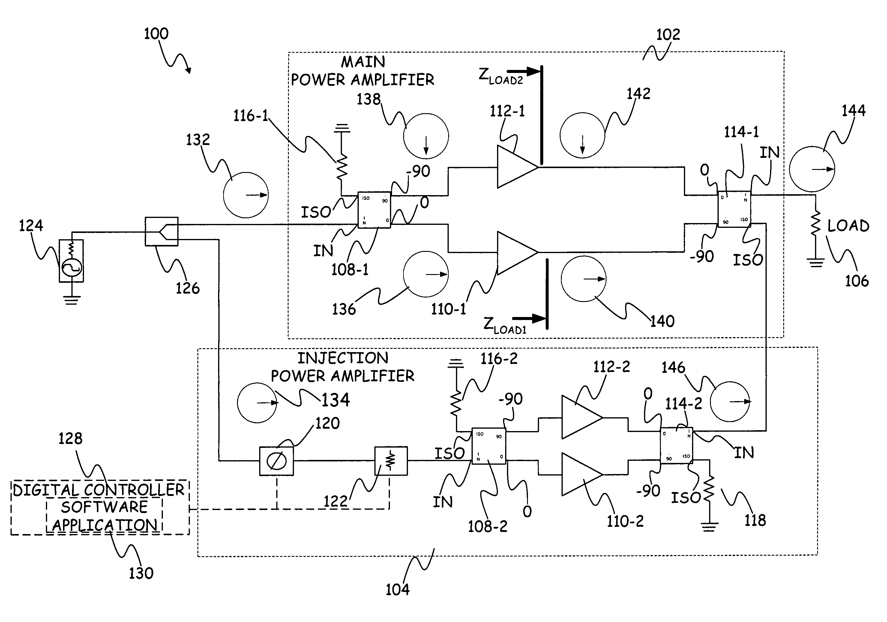
[0011]The present invention relates, in general, to electronically tuned power amplifiers. More specifically, the present invention relates to power amplifier systems that employ quadrature hybrid circuits (described further below) that can be designed to provide a large bandwidth over which the power amplifier can be electronically tuned.

[0012]FIG. 1 is a diagrammatic illustration of a power amplifier apparatus 100 in accordance with an embodiment of the present invention. The primary elements of power amplifier 100 are a main power amplifier circuit 102 and an injection power amplifier circuit 104. In general, main power amplifier circuit 102 includes components that boost a low-power signal to a higher power level, to be delivered to a load (such as 106). The impedance of the main amplifier 102 is normally passively matched to the load 106. This means of matching is normally fixed. Therefore apparatus 100 employs injection amplifier 104, which can provides impedance matching to t...


PUM


Abstract

A power amplifier apparatus that includes a main power amplifier circuit and an injection power amplifier circuit is provided. The main amplifier includes a pair of quadrature coupled amplifiers. Similarly, the injection power amplifier also includes pair of quadrature coupled amplifiers. The output signal from the injection amplifier is connected to the isolation port of the quadrature coupler of the main amplifier. The input signal is split and applied to the inputs of both the main and injection amplifiers. The gain and phase through the injection amplifier is adjusted in order to vary the magnitude and phase of the signal injected into the isolation port of the quadrature combiner of the main amplifier. By varying the magnitude and phase of the injected signal, the impedance seen by the individual amplifiers within main amplifier can be controlled. Controlling these impedances allows the properties of the main amplifier to be dynamically varied.

Description

BACKGROUND OF THE INVENTION[0001]The present invention relates generally to power amplifiers and, more particularly, to electronically tuned power amplifiers.[0002]Power amplifiers boost a low-power signal to a higher power level, to be delivered to a load. The load determines the gain, linearity, and efficiency of the amplifier. Having the ability to dynamically vary this load impedance allows the properties of the amplifier to be dynamically varied.[0003]Current techniques for tuning power amplifiers include mechanical tuning, tuning using electrically variable capacitors or inductors, and injecting a carrier signal using a circulator. Mechanical tuning is employed in “cavity” amplifiers, which include mechanical cavity tuning controls. Here tuning is carried out by mechanically adjusting a cavity dimension. Mechanical tuning is usually slow and cumbersome.[0004]The above-noted electrical tuning techniques (variable capacitors or inductors and injecting a carrier signal using a ci...

Claims


Application Information

Patent Timeline
Patent Type & Authority Patents(United States)
IPC IPC(8): H03F3/68
CPCH03F3/68H03F3/602
Inventor JONES, DAVID E.KOLOSICK, JOSEPH A.
Owner ROCKWELL COLLINS INC
Why Eureka
Try Eureka