Central station monitoring with real-time status and control

a technology of central station and status control, applied in the field of security systems, can solve the problems of lack of control of local security systems, relatively little information provided to central monitoring facilities, and only receiving communications from central monitoring stations, so as to achieve the effect of easy monitoring and information

Active Publication Date: 2007-02-27
ADEMCO INC
View PDF10 Cites 264 Cited by
  • Summary
  • Abstract
  • Description
  • Claims
  • Application Information

AI Technical Summary

Benefits of technology

[0005]The present invention addresses the above and other issue by providing a security system including a central monitoring station that receives periodically updated information from a number of different security systems at different building locations. The central monitoring station can therefore be apprised of all information associated with the security systems, such as whether the security system is armed, in an alarm state, or whether there is a trouble code such as due to a hardware or software problem or maintenance need. Furthermore, a user interface, such as a web browser, at the central monitoring station allows a user to easily monitor, and obtain information from, the different security systems, and to control the different security systems individually or in groups. The invention is particularly suitable for use in monitoring and controlling the security systems of businesses such as chain retail stores, although it is applicable as well to other business and residential settings.

Problems solved by technology

While this approach provides some measure of security, it provides relatively little information to the central monitoring facility.
In particular, the central monitoring station only receives a communication from the security systems when there is an alarm condition.
Moreover, the central station lacks the ability to control the local security systems.

Method used


Image

  • Central station monitoring with real-time status and control
  • Central station monitoring with real-time status and control
  • Central station monitoring with real-time status and control

Examples


Embodiment Construction

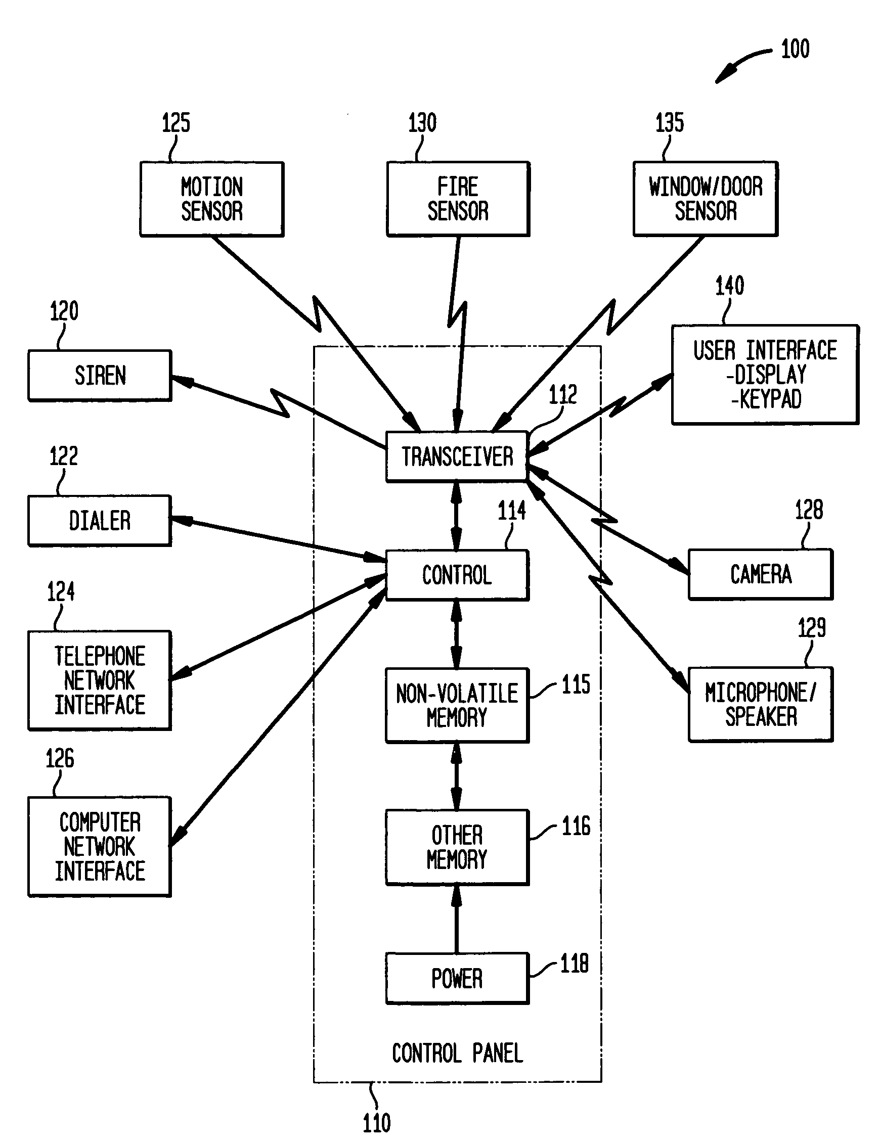
[0016]FIG. 1 illustrates an overview of an example security system, according to the invention, for securing a building location such as a residence or business. The security system 100 includes a central control panel 10 that communicates with a number of sensors via wired or wireless paths. The wireless paths may be RF paths, for instance. The control panel 110 may receive signals from motion sensors 125, fire sensors 130, and window and door sensors 135, for instance.

[0017]Signals received from a peripheral user interface device 140, such as a keypad and display, a combined display and touch screen, and / or a voice interface, may arm and disarm the system. The user interface device 140 may be the primary interface between the human user and the security system 100. The user interface device 140 may include components that are analogous to the control panel 110, including a control, memory and power source. Optionally, the user interface device 140 includes a transceiver (transmitt...


PUM


Abstract

A number of different security systems, such as in home or business locations, periodically transmit status data to a remote facility such as a central monitoring station so that it is continuously informed of the security systems' status. The status may relate to an alarm status, armed status, or trouble code status. A user interface at the remote facility provides a spreadsheet format that allows a user to quickly ascertain the status of the security systems, and to send commands to the security systems. The security systems may be controlled individually or in groups, such as to add or delete authorizations. The user interface can filter or sort the information, or obtain further details. Other information, such as video and audio data from a security system, can also be provided to the remote facility for use in the user interface. Information can be recorded for subsequent playback.

Description

BACKGROUND OF THE INVENTION[0001]1. Field of Invention[0002]The invention relates generally to a security system including a central monitoring station that receive periodically updated information from a number of different security systems at different building locations, and that has the ability to control the different security systems individually or in groups.[0003]2. Description of Related Art[0004]Security systems are commonly used in home and business settings to protect against intruders and other dangers. For example, a chain of retail stores may each have a security system that protects their premises. When an intruder or other alarm condition, such as a fire, is detected, the local security system may report the alarm to a central monitoring facility via a telephone link or other communication link. Personnel at the central monitoring facility may then telephone the local police to report the alarm to have the incident investigated. While this approach provides some mea...

Claims


Application Information

Patent Timeline
Patent Type & Authority Patents(United States)
IPC IPC(8): G08B1/00
CPCG08B13/19682G08B13/19689H04N7/181G08B13/19697G08B25/08G08B13/19693G08B25/008
Inventor SIMON, SCOTTHOPE, GORDONBLUM, WILLIAM R.
Owner ADEMCO INC
Why Eureka
Try Eureka