Optical system for torsion oscillator laser scanning unit

a laser scanning and optical system technology, applied in the field of optical systems, can solve problems such as inacceptable print defects in laser printer applications

Active Publication Date: 2007-02-27
LEXMARK INT INC
View PDF13 Cites 64 Cited by
  • Summary
  • Abstract
  • Description
  • Claims
  • Application Information

AI Technical Summary

Benefits of technology

[0010]In another aspect, the invention provides an optical imaging system comprising a light source, pre-scan optics, a bidirectional scanning torsion oscillator, post-scan optics, and an imaging device. According to the invention, the light source, such as a laser diode, produces a light beam that propagates along an optical path. The pre-scan optics receive the light beam, directs it to a reflective surface of the scanning torsion oscillator, and modifies the divergence of the light beam in the scan direction. The scanning torsion oscillator receives the light beam from the pre-scan optics and reflects the beam from the reflective surface that oscillates according to a sinusoidal function. Based on the motion of the reflective surface, the torsion oscillator causes the reflected light beam to scan back and forth at a sinusoidal angular rate across an imaging surface of the imaging device. In this manner, the beam is scanned from a first edge position through a central position to a second edge position on the imaging surface.
[0011]The post-scan optics are positioned in the optical path of the beam between the torsion oscillator and the imaging surface of the imaging device. The post-scan optics receive the reflected light beam from the scanning torsion oscillator and cause deflection of the reflected light beam in the scan direction. According to the invention, the beam deflection in the scan direction introduced by the post-scan optics is greater at the first and second edge positions of the imaging surface than at the central position. Due to varying levels of the post-scan beam deflection, the scan rate of the light beam at the first and second edge positions is substantially equivalent to the scan rate at the central position. In this manner, the post-scan optics compensate for imaging errors associated with the sinusoidal scan rate of the light beam reflected from the torsion oscillator.

Problems solved by technology

This causes linearity errors at the ends of the scan line which results in unacceptable print defects in a laser printer application.

Method used


Image

  • Optical system for torsion oscillator laser scanning unit
  • Optical system for torsion oscillator laser scanning unit
  • Optical system for torsion oscillator laser scanning unit

Examples


Embodiment Construction

[0020]Prior patents assigned to the assignee of the present invention have described the construction and operation of the torsion oscillator, including the placement of coil(s) and magnet(s) that together create rotational movement when electrical drive power is applied to the coil. These prior patents include: U.S. Pat. No. 6,838,661 which issued Jan. 4, 2005; U.S. Pat. No. 6,870,560 which issued Mar. 22, 2005; and U.S. Pat. No. 6,794,794 which issued Sep. 21, 2004, the entire disclosures of which are hereby expressly incorporated by reference.

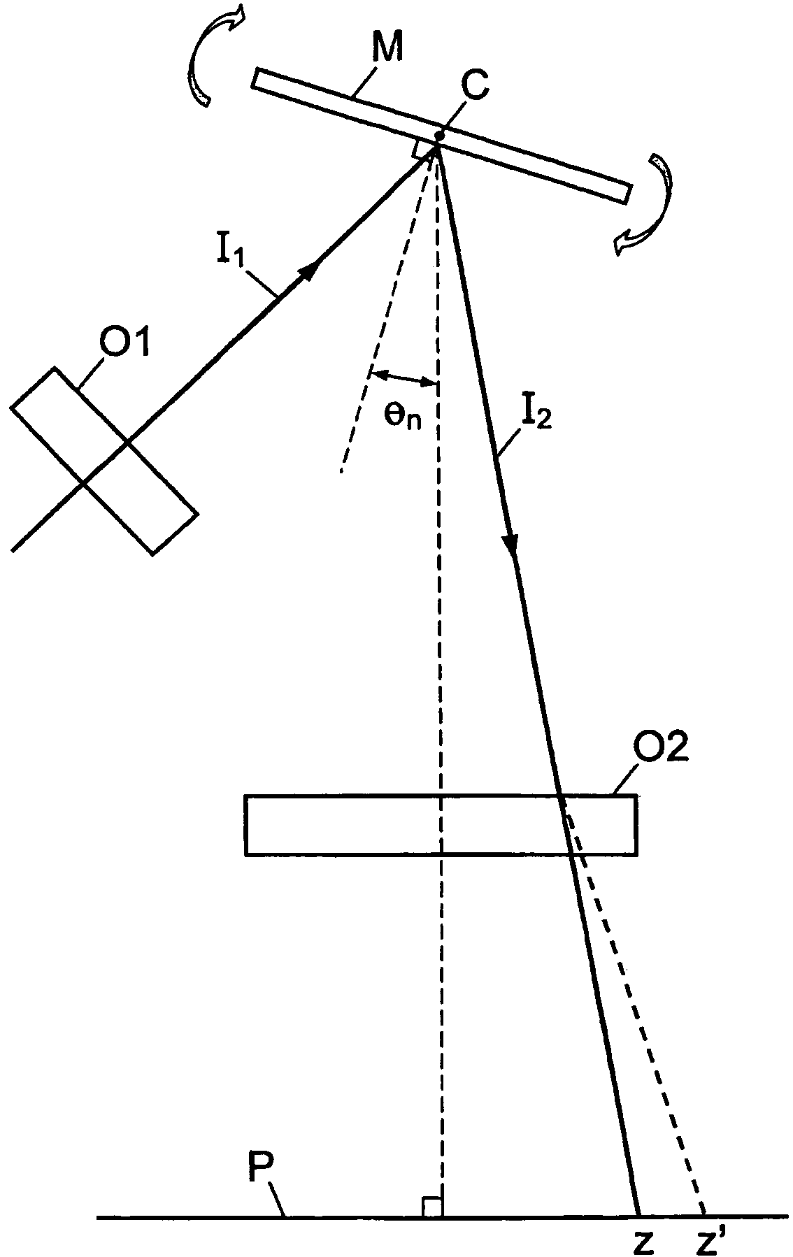
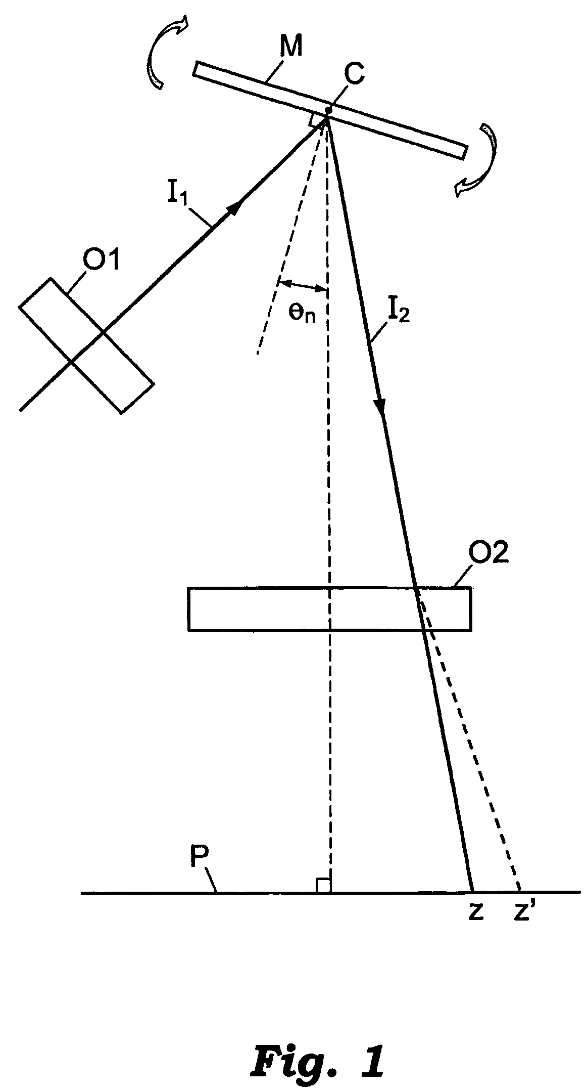
[0021]The nature of the problem solved by the present invention is depicted in FIG. 1. A rotational planar mirror M in a laser printer, having a center of rotation C, deflects a laser light beam I1 to form a reflected beam I2. Prior to reflection from the mirror M, the beam I1 intersects an optical system O1 of lenses and / or mirrors. The angular rotation of the mirror M about the center C is a periodic function of time. The reflected beam I2...


PUM


Abstract

An optical apparatus compensates for imaging errors associated with the sinusoidal angular scan rate of a light beam reflected from a bidirectional scanning torsion oscillator. The compensation is achieved by a combination of pre-scan optics positioned between the source of the light beam and the scanning torsion oscillator, and post-scan optics positioned between the scanning torsion oscillator and an imaging surface of an imaging device. Based on the optical characteristics of its components, the post-scan optical system causes deflection of the light beam in the scan direction. To compensate for the sinusoidal scan rate, the deflection caused by the post-scan optical system is greater at the opposing edge positions of the imaging surface than at a central position. In this manner, the scan rate of the light beam at the first and second edge positions is substantially equivalent to the scan rate at the central position. The pre-scan optical system directs the light beam onto the reflective surface of the torsion oscillator in a manner that compensates for divergence of the light beam in the scan direction caused by the post-scan optical system.

Description

[0001]This application is a continuation-in-part of U.S. patent application Ser. No. 10 / 689,175, filed Oct. 20, 2003 now U.S. Pat. No. 6,794,794, entitled BI-DIRECTIONAL GALVONOMETRIC SCANNING AND IMAGING, which issued as U.S. Pat. No. 6,794,794 on Sep. 21, 2004.BACKGROUND OF THE INVENTION[0002]The invention relates generally to optical systems used in laser printers, and, more particularly, to an optical lens system for correcting linearity errors associated with torsion oscillator mirrors having a sinusoidal scan angle motion.[0003]Torsion oscillators with a mirrored surface are used in laser printers to scan a laser beam bi-directionally across a laser printer drum. Generally, the scan angle of the mirrored surface of the torsion oscillator varies sinusoidally with respect to time. At the angular extremes of the sinusoidal motion—the point at which the scan reverses direction—the rate of change of the scan angle slows to zero. Due to the decreasing rate of angular change at the s...

Claims


Application Information

Patent Timeline
Patent Type & Authority Patents(United States)
IPC IPC(8): G02B26/08G02B26/10
CPCG02B26/105
Inventor CANNON, ROGER STEVENROUTT, JR., WILSON MORGAN
Owner LEXMARK INT INC
Why Eureka
Try Eureka