
Durable electrophotographic prints

a toner fusing and electrophotography technology, applied in the direction of electrophotography process apparatus, optics, instruments, etc., can solve the problems of easy damage to the fused toner image on the receiver member, easy damage to the fused toner image, and customer damage to the color print made by the electrophotographic reproduction apparatus, etc., to achieve the effect of durable surfa

Active Publication Date: 2007-02-27
EASTMAN KODAK CO
View PDF21 Cites 23 Cited by
  • Summary
  • Abstract
  • Description
  • Claims
  • Application Information

AI Technical Summary

Benefits of technology

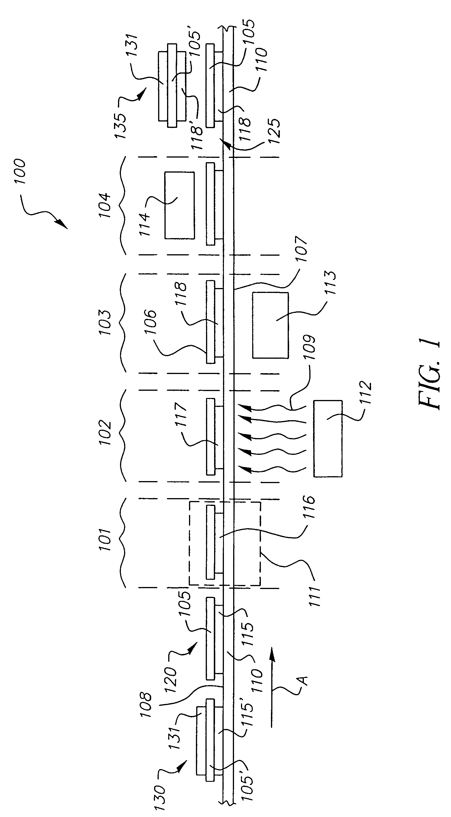
[0023]The subject invention is a glossing apparatus for UV-crosslinking and glossing a toner image on a receiver member. The glossing apparatus employs direct contact between a UV-curable toner and a smooth UV-transparent movable web, the glossing apparatus incorporating a plurality of processing zones including: a heating zone for melting UV-curable toner under pressure, an exposure zone for curing melted UV-curable toner via UV radiation, a cooling zone, and a separation zone for separating UV-cured glossed toner images from the web. The glossing apparatus can provide a durable surface on an output member having a substantially uniform gloss, e.g., in a pictorial area.

Problems solved by technology

Color prints made by electrophotographic reproduction apparatus, especially high gloss prints, can be subject to damage by a customer, e.g., by rubbing, abrasion, or scratching.
This is particularly the case for high quality glossy photographic prints made from very small toner particles, for which the high quality can be compromised quite easily because the toner layers are comparatively thin and therefore more readily damaged.
Moreover, a fused toner image on a receiver member can suffer from cracking damage when the print is bent.

Method used


Image

  • Durable electrophotographic prints
  • Durable electrophotographic prints
  • Durable electrophotographic prints

Examples


embodiment 200

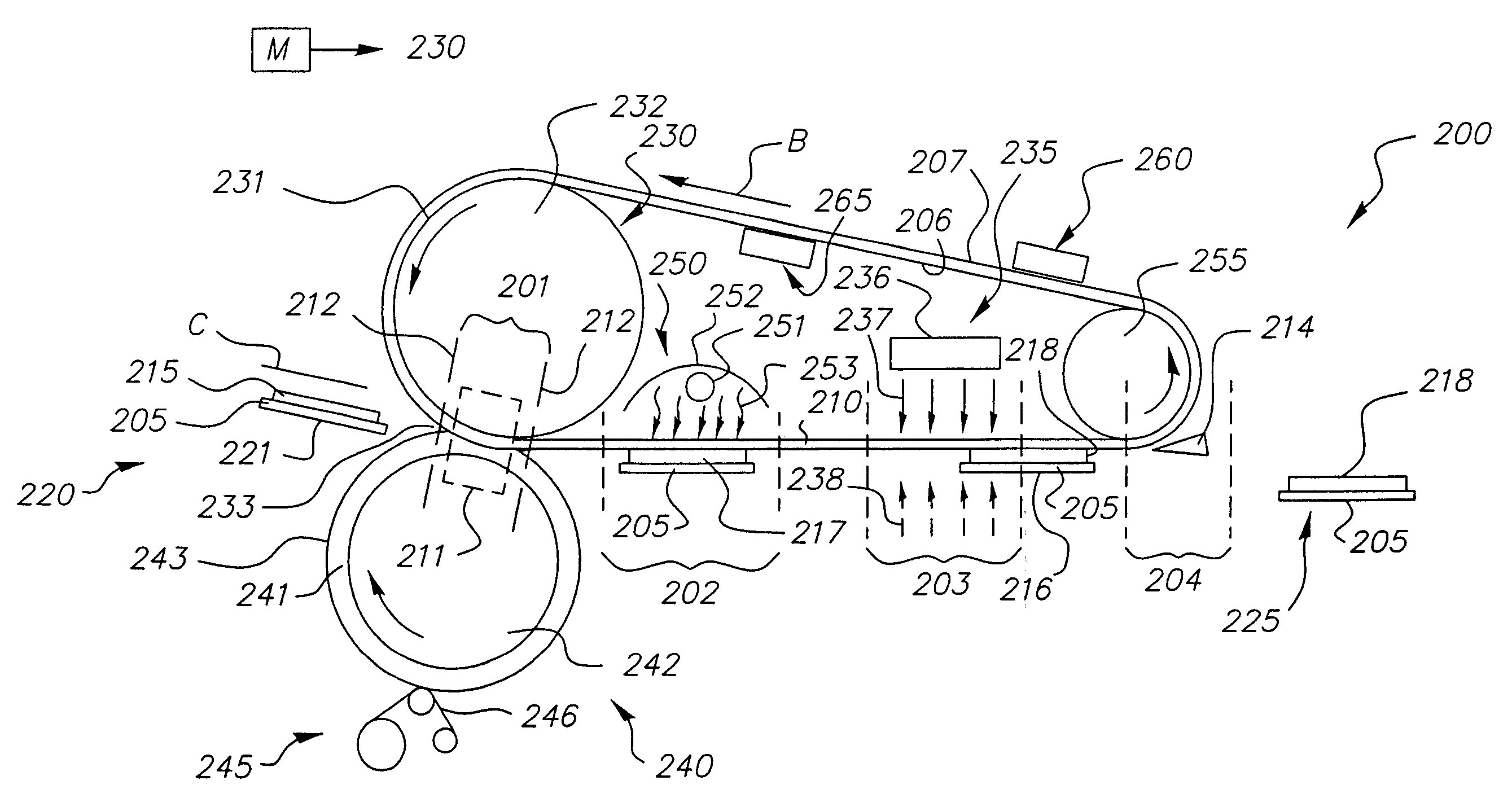
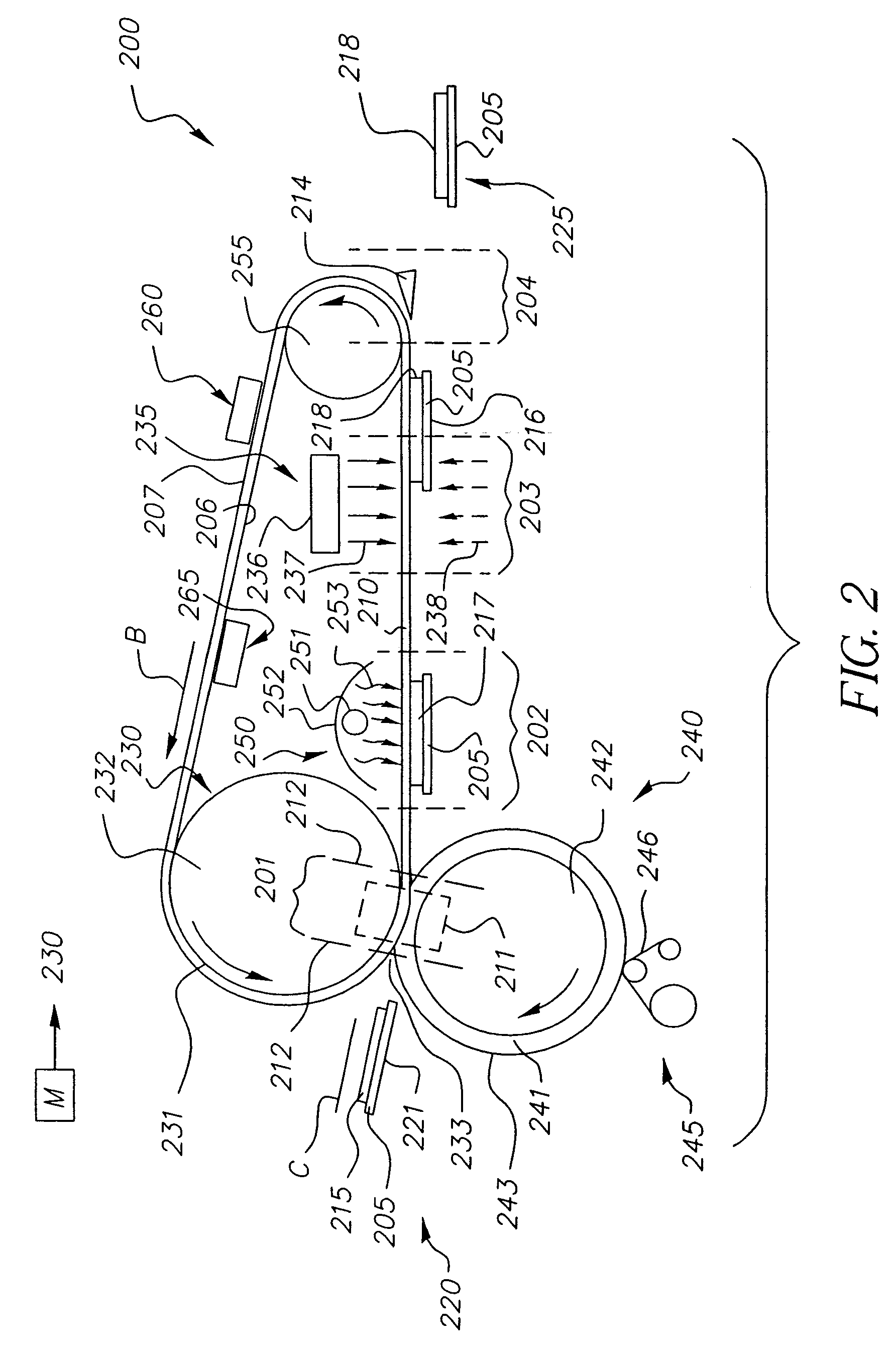
[0068]In embodiment 200, the heating mechanism in heating zone 201 includes the hot contact area of the nip 233 (shown enclosed in FIG. 2 by the dotted line 211). The heating zone 201 can extend beyond the contact area of the nip, as indicated by the dashed lines 212, e.g., because of heat radiated outside of the nip by roller 230. Furthermore, a post-nip wrap of belt 210 around roller 230 can be provided so as to extend the heating zone beyond the actual contact area of the nip (post-nip wrap not illustrated).

[0069]Roller 230 is required to be sufficiently hot so as to melt at least UV-curable toner in contact with surface 207 of belt 210. Moreover, fusing temperature in nip 233 must be high enough so that the molten state of UV-curable toner persists while receiver member 205 is moved toward and into the exposure zone 202. However, with a UV-curable colorless or clear toner outermost in pre-gloss toner image 215, it is preferred that melted outermost toner particles do not flow in...

embodiment 500

[0088]To make a duplex glossed print in embodiment 500, a stack simplex prints can taken from tray 520 and put through a conventional electrophotographic reproduction apparatus (not shown) so as to form on each of the opposite faces a new pre-gloss toner image, and the stack returned to accessory unit 500 for these pre-gloss toner images to be glossed in manner as described above for the simplex prints. Preferably, for making duplex UV-glossed prints, each of the sheets initially placed in stack 512 has on each face a preferably pre-fused pre-gloss image, so that after one set of faces has been UV-glossed, the output members from the first glossing are removed from tray 520 and placed into housing 511 so that in a second glossing the opposing faces can be UV-glossed. To make “mixed” prints, simplex UV-glossed output members are delivered from tray 520 to a conventional electrophotographic reproduction apparatus (not shown) so that non-glossed toner images can be formed on the opposi...

embodiment 550

[0099]FIGS. 7a, b show block diagram sketches featuring an accessory unit embodiment 550 which includes UV-glossing apparatus of the invention for making simplex and duplex prints. Accessory 550 is preferably used as a stand-alone “near-line” unit, but is not restricted to such usage. Within unit 550 are included a UV-glossing (UVG) apparatus 552 of the invention and a colorless toner module (CTM) 551.

[0100]FIG. 7a illustrates how embodiment 550 can be used to UV-gloss one side of an input member (RS) 565, which is a receiver member carrying a simplex color toner image. This color toner image is preferably made from conventional (non-UV-curable) color toner, which color toner is preferably fused. Input member RS is moved along path k, into the accessory 550 and is first processed by being passed through the colorless toner module 551. In CTM 551, a layer of preferably colorless UV-curable toner particles is deposited in juxtaposition with the simplex color toner image, following whi...


PUM


Abstract

UV-glossing for simplex and duplex prints, wherein an input member having thereon a pre-gloss toner image including UV-curable toner is moved, in non-slip association with a smooth UV-transparent web, jointly with the web through a plurality of process zones sequentially including a heating zone and an exposure zone, thereby producing an output member having a glossed, UV-cured, surface. In the heating zone, at least the outermost toner of the pre-gloss toner image is heated to a molten state in contact with the web. In the exposure zone, with the molten state being maintained, at least the outermost toner which contacts the web is cured by a flux of UV radiation transmitted through the web. In a preferred embodiment, the UV-curable toner is formed as an outer layer on the pre-gloss toner image.

Description

CROSS REFERENCE TO RELATED APPLICATIONS[0001]This is a 111A application of Provisional Application Ser. No. 60 / 553,740, filed Mar. 17, 2004.FIELD OF THE INVENTION[0002]The invention relates to electrophotography and to toner fusing apparatus, and in particular to belt fusing apparatus and method wherein toner in a molten state is UV-cured to produce durable toner images on receiver members.BACKGROUND OF THE INVENTION[0003]In an electrophotographic apparatus, e.g., a reproduction or printing machine, unfused toner images are formed on receiver members, and the toner images are then fused or fixed to receiver members in a fusing station employing heat and / or pressure. The receiver members are typically sheets of paper or transparency stock. The resulting output prints can be simplex (image on one side only) or duplex. A duplex print can be made by forming an unfused toner image on one side of a receiver member, fusing it, then forming an unfused toner image on the other side of the re...

Claims


Application Information

Patent Timeline
Patent Type & Authority Patents(United States)
IPC IPC(8): G03G15/20
CPCG03G15/2007G03G15/2021G03G15/2028G03G15/6585G03G2215/2016G03G2215/2032G03G2215/00805G03G2215/2083G03G15/2098
Inventor TOMBS, THOMAS N.
Owner EASTMAN KODAK CO
Learn More