Rich quick mix combustion system

a combustion system and quick mix technology, applied in the direction of engine starters, engine/propulsion engine ignition, lighting and heating apparatus, etc., can solve the problems of high flame temperature, nox generation, and excessive stoichiometric fuel in the rich burn zone,

Active Publication Date: 2007-03-06
HONEYWELL INT INC
View PDF21 Cites 110 Cited by
  • Summary
  • Abstract
  • Description
  • Claims
  • Application Information

AI Technical Summary

Problems solved by technology

Concurrently, the fuel nozzle may introduce a stoichiometrically excessive quantity of fuel into the rich burn zone.
Initially, the fuel-air ratio of the combustion products may change from fuel rich to stoichiometric, which may cause an attendant rise in the combustion flame temperature.
However, until the mixture is diluted to a fuel-air ratio substantially lower than stoichiometric, the flame temperature remains high enough to generate considerable quantities of NOx.
Because most of the NOx emissions originate during the quenching process, it may be beneficial for the quenching to progress rapidly, thus limiting the time available for NOx formation.
Because of the elevated fuel-air ratio, fuel rich pockets may burn hotter than the rest of the mixture, thereby promoting additional NOx formation and generating local “hot spots” or “hot streaks” that may damage the turbine.
Snyder may thus result in a complicated arrangement, wherein the heat shields may be cooled using film cooling holes that penetrate through each heat shield, and each shell may be cooled using impingement cooling holes that penetrate through each shell.

Method used


Image

  • Rich quick mix combustion system
  • Rich quick mix combustion system
  • Rich quick mix combustion system

Examples


Embodiment Construction

[0024]The following detailed description is of the best currently contemplated modes of carrying out the invention. The description is not to be taken in a limiting sense, but is made merely for the purpose of illustrating the general principles of the invention, since the scope of the invention is best defined by the appended claims.

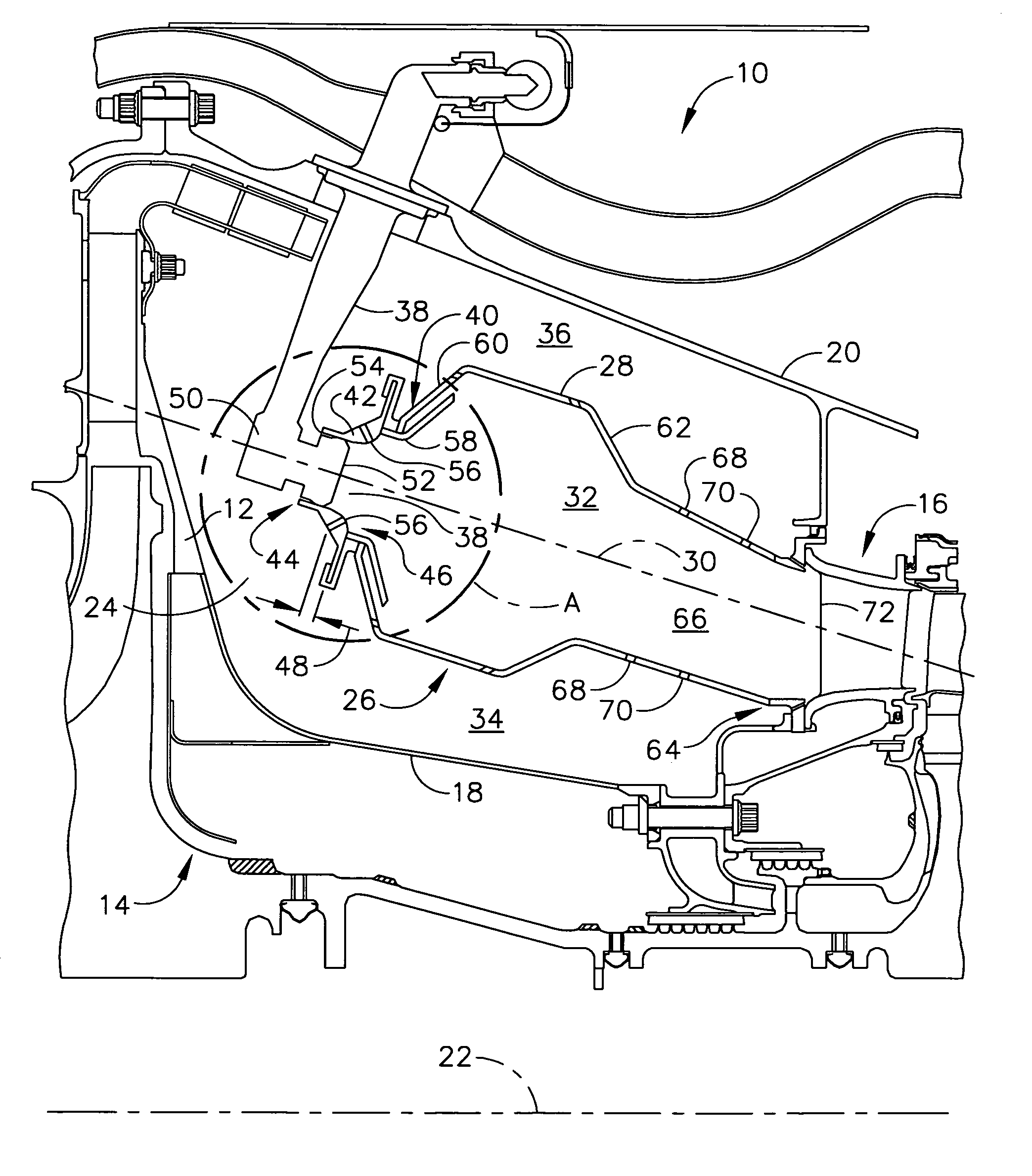
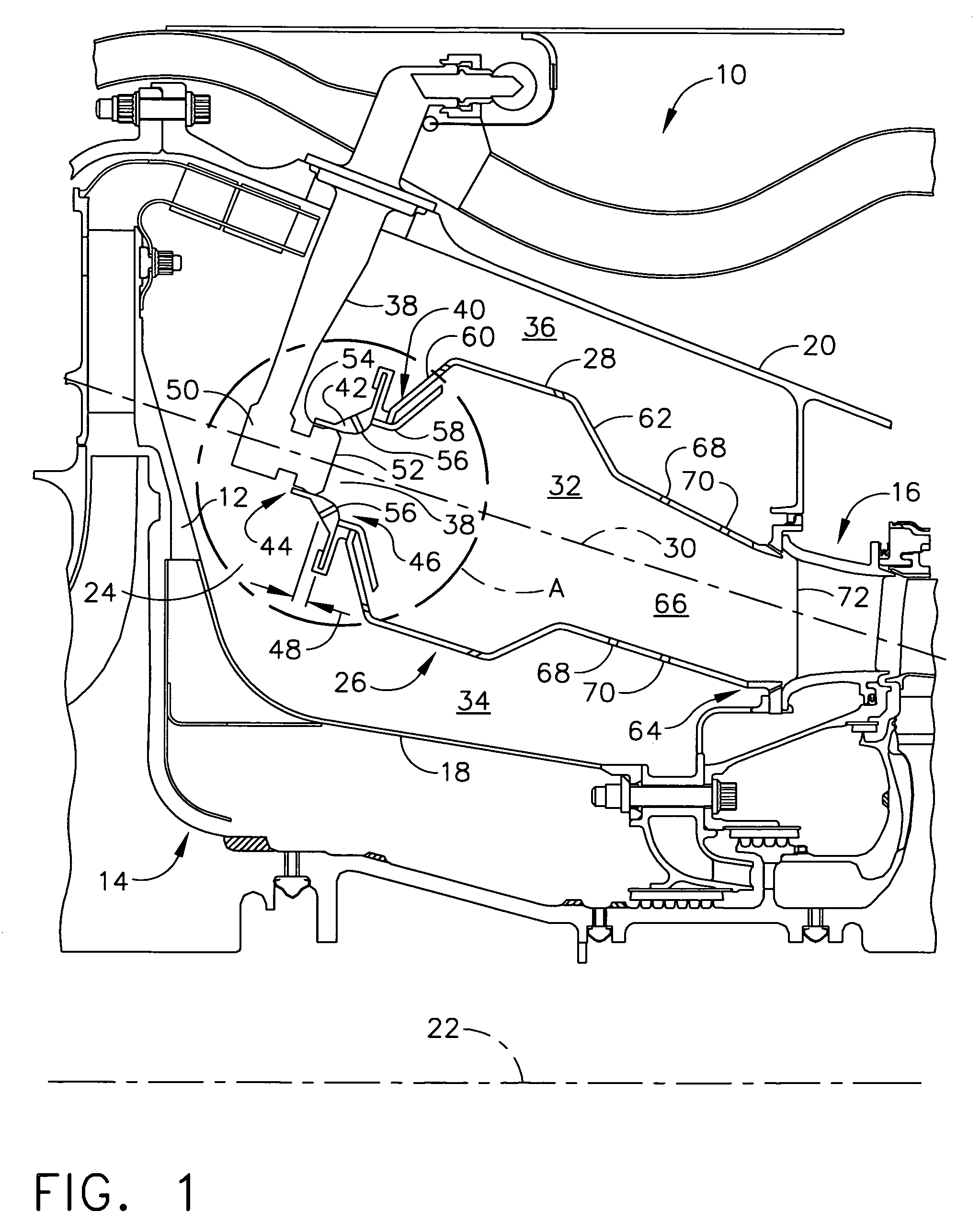
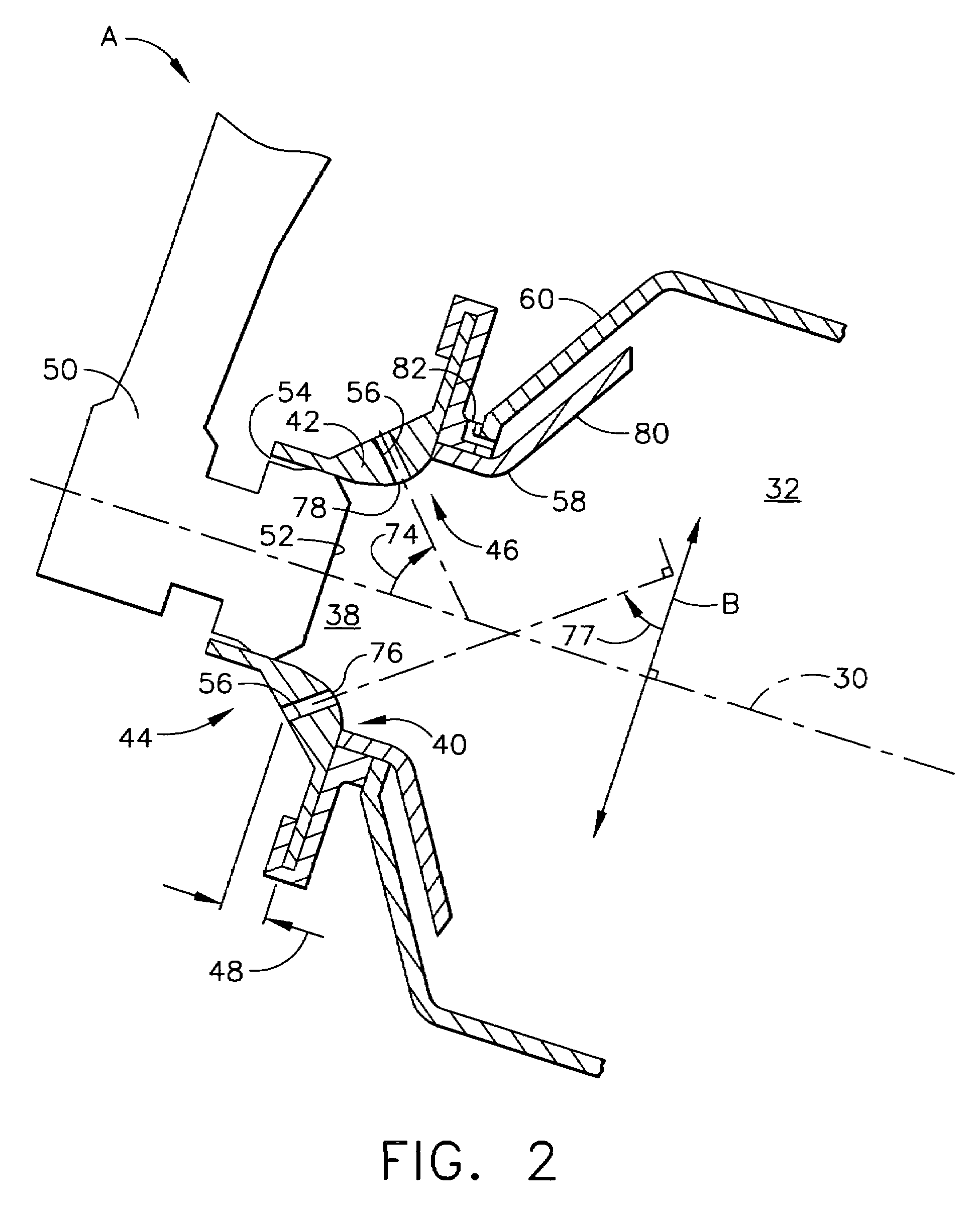
[0025]Broadly, the present invention generally provides a gas turbine having a combustion chamber comprising a premix chamber. The premix chamber comprises a cylindrical chamber having a chamber inlet end longitudinally separated from a chamber outlet end along a central axis (e.g., a combustor centerline). Directly upstream of, and in physical communication with, the chamber inlet end may be a chamber inlet plate through which may be disposed a fuel nozzle and a plurality of swirler passages. This is in contrast to the prior art, wherein a separate swirler is mounted to the chamber inlet plate.

[0026]Also, the premix chamber of the present invention may...


PUM


Abstract

A premix chamber for a combustor of a gas turbine engine comprises a cylindrical chamber having a premix chamber wall, the cylindrical chamber having a chamber inlet end longitudinally separated from a chamber outlet end along a central axis, a chamber inlet plate in communication with the premix chamber wall at the chamber inlet end, the chamber inlet plate having a fuel nozzle inlet hole disposed through the chamber inlet plate, the chamber inlet plate further comprising a plurality of swirler passages disposed through the chamber inlet plate, and the chamber outlet end being open. A method of producing turbine gas is also disclosed.

Description

BACKGROUND OF THE INVENTION[0001]The present invention generally relates to an apparatus and method for a rich, quick mix combustion system that provides low levels of NOx, carbon monoxide, unburned hydrocarbons, and smoke. More specifically, the present invention relates to an apparatus and method for a rich, quick mix combustion system comprising a premixing chamber located upstream of a combustion chamber.[0002]Gas turbine engines, such as those which may be used to power modern commercial aircraft, may include a compressor for pressurizing a supply of air, a combustor for burning a hydrocarbon fuel in the presence of the pressurized air, and a turbine for extracting energy from the resultant combustion gases. The combustor may include radially spaced apart inner and outer liners. The liners may define an annular combustion chamber that resides axially between the compressor and the turbine. Arrays of circumferentially distributed combustion air holes may penetrate each liner at ...

Claims


Application Information

Patent Timeline
Patent Type & Authority Patents(United States)
IPC IPC(8): F23R3/14F23R3/06F23R3/30F23R3/28F23R3/42F23R3/50F23R3/58
CPCF23R3/286F23R3/50F23R3/30
Inventor DUDEBOUT, RODOLPHEKUHN, TERREL E.YANKOWICH, PAUL R.ZUPANC, FRANK J.
Owner HONEYWELL INT INC
Why Eureka
Try Eureka