Variable stroke engine

a variable-strength, engine technology, applied in the direction of valve details, valve arrangements, valve drives, etc., can solve the problems of increasing over-all complex structure of the engine, etc., to reduce the overall dimension of the engine, reduce the mechanical noise and friction loss, and reduce the total number of structural components

Inactive Publication Date: 2007-03-06
HONDA MOTOR CO LTD
View PDF25 Cites 36 Cited by
  • Summary
  • Abstract
  • Description
  • Claims
  • Application Information

AI Technical Summary

Benefits of technology

[0008]It is also an object of the present invention to provide a variable stroke engine that reduces the overall dimensions of the engine, reduces the number of structural components, and concurrently reduces the amount of mechanical noise and friction loss.
[0010]In accordance with such an arrangement, because the cam is provided on the rotating shaft having the eccentric shaft, it is unnecessary to use a camshaft and rotating shaft. As a result, the total number of structural components is reduced. Further, space is not required to be provided to arrange the camshaft, thereby reducing the overall dimensions of the engine. Furthermore, since a dedicated camshaft is not needed, a power transmission mechanism is not required to be positioned between the crankshaft and the dedicated camshaft, thereby reducing the amount of mechanical noise and friction loss.
[0011]Furthermore, in accordance with a second aspect of the present invention, in addition to the arrangement of the first aspect, a variable stroke engine includes an intake cam, an exhaust cam, and an eccentric shaft disposed between the intake and exhaust cams all of which are integrally provided on the rotating shaft. The eccentric shaft has a diameter that covers the entire shape of one of the intake and exhaust cams when viewed from a direction along the axis of the rotating shaft. In accordance with such an arrangement, the eccentric shaft can be provided on the rotating shaft without using a crank arrangement for the rotating shaft, the machining precision of the eccentric shaft and the intake and exhaust cams is improved, and the rotating shaft is formed with relatively low weight and increased rigidity.

Problems solved by technology

In the conventional OHV variable stroke engine, a reduction gear positioned between the crankshaft and the camshaft causes mechanical noise, and the overall complicated structure of the engine increases friction loss.

Method used


Image

  • Variable stroke engine
  • Variable stroke engine
  • Variable stroke engine

Examples


Embodiment Construction

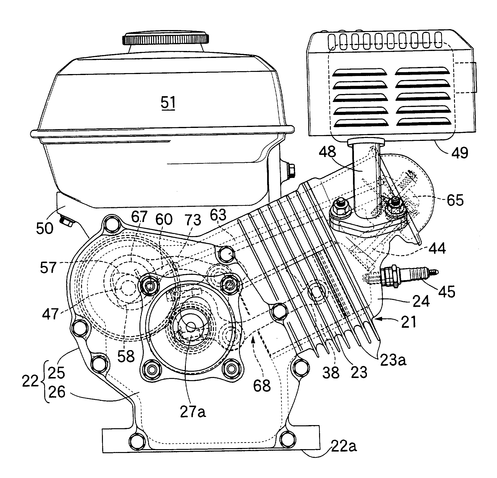
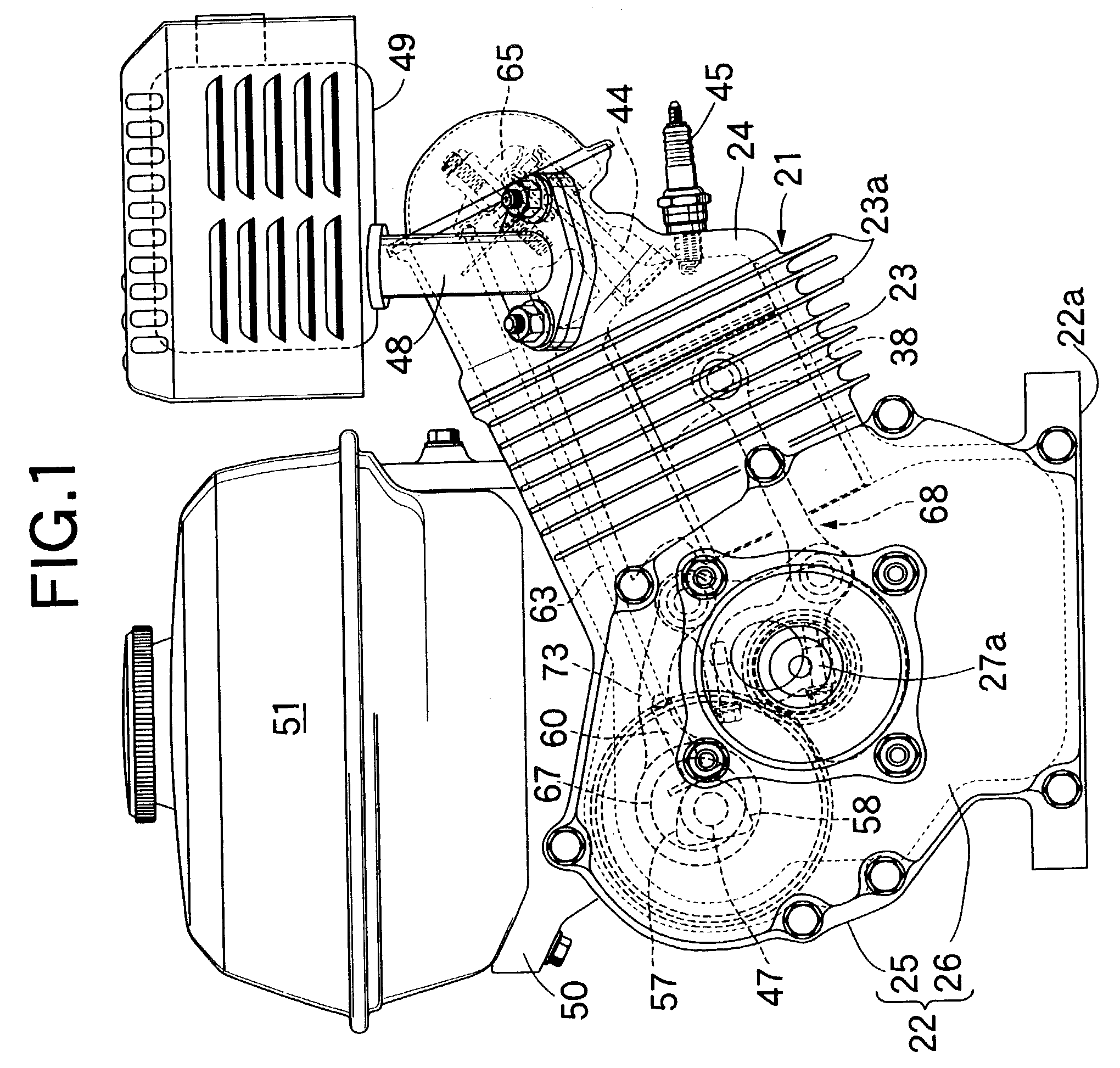
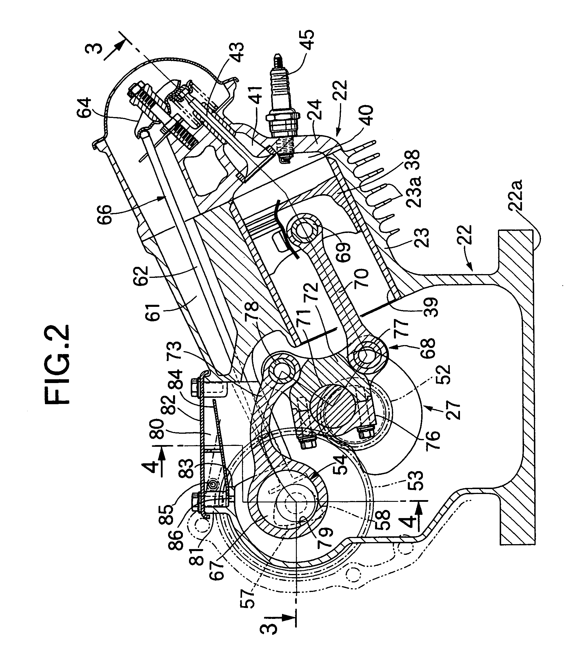
[0018]A preferred embodiment of the present invention is explained with reference to FIGS. 1 to 5. Referring to FIGS. 1 to 3, the illustrated engine is an air-cooled single cylinder engine used in, for example, work equipment. An engine main body 21 is formed from a crankcase 22, a cylinder block 23, and a cylinder head 24 joined to the head of the cylinder block 23. The cylinder block 23 is inclined slightly upward and projects from a side face of the crankcase 22. A plurality of air-cooling fins 23a, 24a are provided on the outer side faces of the cylinder block 23 and the cylinder head 24, respectively. The crankcase 22 is mounted on an engine bed of various types of work equipment via a mounting face 22a on a lower face of the crankcase 22.

[0019]The crankcase 22 is formed from a case main body 25 and a side cover 26 joined to an open end of the case main body 25. The case main body 25 is integrally mold-cast with the cylinder block 23. Opposite ends of a crankshaft 27 are rotata...


PUM


Abstract

A variable stroke engine includes a connecting rod having one end thereof connected to a piston via a piston pin. A sub-rod is connected to a crankshaft via a crankpin and to the other end of the connecting rod. A control rod has one end thereof connected to the sub-rod at a position distal from the position where the sub-rod is connected to the connecting rod. An eccentric shaft is connected to the other end of the control rod. The eccentric shaft is provided at a position eccentric relative to a rotating shaft to which power is transmitted from the crankshaft at a reduction ratio of ½. Intake and exhaust cams form a part of a valve operating mechanism and are provided on the rotating shaft.

Description

BACKGROUND OF THE INVENTION[0001]1. Field of the Invention[0002]The present invention relates to a variable stroke engine having a connecting rod with one end thereof connected to a piston via a piston pin, a sub-rod connected to a crankshaft via a crankpin and to the other end of the connecting rod, and a control rod with one end thereof connected to the sub-rod at a position distal from the position where the connecting rod is connected. In particular, the present invention relates to a variable stroke engine also having an eccentric shaft connected to the other end of the control rod, wherein the eccentric shaft is provided at a position eccentric relative to a rotating shaft to which power is transmitted from the crankshaft at a reduction ratio of ½.[0003]2. Description of the Related Art[0004]Conventionally, such a variable stroke engine is known, such as, for example, the engine disclosed in U.S. Pat. No. 4,517,931 to Nelson.[0005]In the case of a DOHC or SOHC variable stroke ...

Claims


Application Information

Patent Timeline
Patent Type & Authority Patents(United States)
IPC IPC(8): F02D15/02F01L1/04F02B75/04F01L1/02F01L1/10F02B41/04F02B75/02F02B75/16F02B75/32
CPCF01L1/024F02B41/04F02B75/048F02D15/02F02B75/16F02B2075/027F02B2275/34F02B75/04
Inventor SATO, YOSHIKAZUWATANABE, SEI
Owner HONDA MOTOR CO LTD
Why Eureka
Try Eureka