Homogenizing optical sheet, method of manufacture, and illumination system

a technology of optical sheets and homogenizing sheets, applied in the field of homogenizing optical sheets, method of manufacture, and illumination systems, can solve the problems of reducing the contrast of the display system, affecting the light efficiency, and high voltage requirements of typical fluorescent backlights

Active Publication Date: 2007-03-06
POWELL KARLTON DAVID +1
View PDF7 Cites 58 Cited by
  • Summary
  • Abstract
  • Description
  • Claims
  • Application Information

AI Technical Summary

Benefits of technology

[0016]It is an object of the present invention to provide a single light homogenizing optical sheet that provides uniform intensity across and within an area located within a plane substantially parallel and located after the optical sheet.
[0017]It is an object of the present invention to provide such an optical sheet that exhibits lower scatter and allows higher input acceptance angles as well as higher output exit angles than achieved with optical sheets used in the prior art.
[0018]It is an object of the present invention to provide such an optical sheet that can be made of flexible material thereby enabling it to be shaped about a substantially curved surface.

Problems solved by technology

Typical fluorescent backlights have high voltage requirements and relatively short lifespans.
In addition, much of the light from fluorescent backlighting exhibits high angular frequencies that can contribute to scatter, potentially reducing display system contrast.
Substantially collimated and uniform backlight can be realized using such a system, however, light efficiency can be affected.
One drawback with using two optical sheets with microlens arrays formed on one surface is that they must be relatively aligned to a high degree of accuracy, limiting the use of dual MLA homogenizer to high-cost applications having assemblies with more complex mounting techniques in order to align and keep registration.
Another drawback is limited acceptance angle that can be achieved, due to Total Internal Reflection (TIR) limitations of the first array.
A third drawback is scatter caused by the TIR limitations.
A fourth drawback is limited exit angle that can be achieved due to TIR limitations of the first array as well as realistic limitations due to refractive index relationships.
It should be noted that such a system only allows uniformity versus position across the film plane and does not address uniformity versus angle within the film gate.
Although not obvious, two opposingly faced microlens arrays in tandem at the focal length separation distance have inherent design limitations on exit Numerical Aperture extent due to the effect of total internal reflection.
In addition, uniformity versus angle at the output plane is not achieved with such system.
Also, substantially aspheric profiles for high numerical aperture lenslets are not possible using the method of isotropic etching through pinholes.

Method used


Image

  • Homogenizing optical sheet, method of manufacture, and illumination system
  • Homogenizing optical sheet, method of manufacture, and illumination system
  • Homogenizing optical sheet, method of manufacture, and illumination system

Examples


Embodiment Construction

)

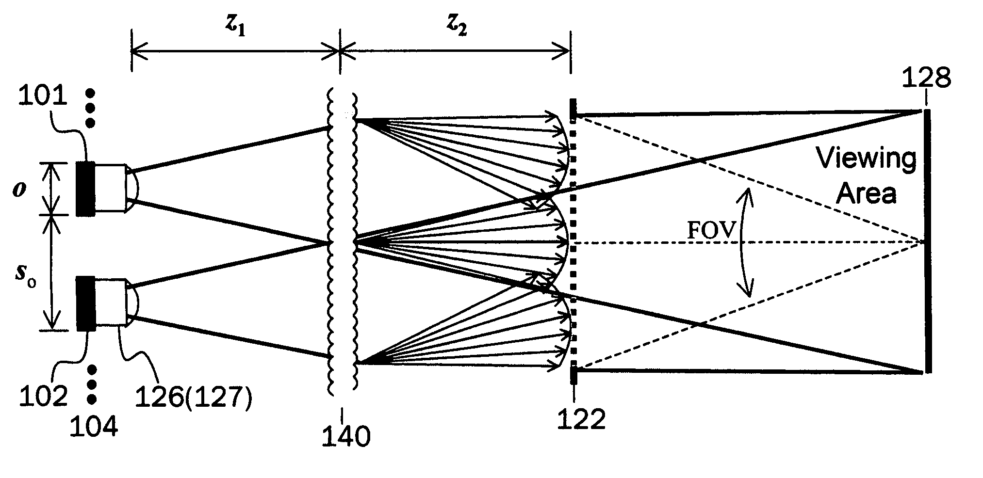
[0064]Referring to the accompanying FIGS. there is shown an optical sheet 10 that exhibits the property of accepting light equal to or within a designed input acceptance cone angle, or Numerical Aperture, then redirecting the input light as output into a constant design exit cone, exiting substantially normal to the sheet surface such that the light intensity within the cone is substantially uniform in intensity versus angle. It should be noted that the optical sheet 10 can function for a continuum of wavelengths of visible light as well as ultraviolet, infrared, far-infrared, and other radiation wavelength ranges, depending on the choice of material used to form the sheet. Further, it should be noted that choice of a material exhibiting substantially high transparency and limited dispersion throughout a given spectrum provides for a radiation homogenizing optical sheet that functions substantially consistent for all wavelengths within such wavelength spectrum. For such case, the s...


PUM

PropertyMeasurementUnit
exit anglesaaaaaaaaaa
propagation distanceaaaaaaaaaa

Abstract

An optical sheet that accepts light transmitted at or within a specific entrance cone angle that then redirects and transmits the light within an exit cone that is substantially normal to the sheet's plane. The intensity of the light within the exit cone is substantially uniform for any light source entering the sheet within the sheet's acceptance angle. The optical sheet is made of transparent material with microlens arrays formed on its opposite front and back surfaces. The thickness of the optical sheet is sufficient so that the microlens on the opposite surfaces are separated a distance equal to the microlens focal length, with each microlens on the front and back surfaces having substantially similar size and shape, with centers transversely aligned. When used with one or more light sources located on one surface, the transmitted light through the optical sheet is uniform in intensity across a second surface. When used with a second optical sheet, aligned parallel to the first optical sheet, the transmitted light is uniform across and throughout angles within the exit cone at a second surface. An economical method of manufacturing the optical sheet is also provided.

Description

[0001]This utility patent application is based on the U.S. provisional patent application (Ser. No. 60 / 437,657) filed on Dec. 31, 2002.BACKGROUND OF THE INVENTION[0002]1. Field of the Invention[0003]The present invention relates to a light homogenizing optical sheet used to create uniform light, a method of manufacturing the optical sheet, and a backlight system that uses the optical sheet for a display device.[0004]2. Description of the Related Art[0005]While a variety of solid-state display devices have been developed in the past, Liquid Crystal Displays (LCDs) are attractive due to low cost, reliability, low power and voltage requirements, longevity, and availability. Typical fluorescent backlights have high voltage requirements and relatively short lifespans. In addition, much of the light from fluorescent backlighting exhibits high angular frequencies that can contribute to scatter, potentially reducing display system contrast.[0006]Due to the advantages of solid-state performa...

Claims


Application Information

Patent Timeline
Patent Type & Authority Patents(United States)
IPC IPC(8): F21V5/00G02B3/00G02B27/09G02F1/1335
CPCG02B3/0025G02B3/0031G02B3/005G02B3/0056G02B3/0062G02B3/0068G02B19/0014G02B27/0927G02B27/0961G02F1/133526G02B19/0066G02B19/0095G02B27/09
Inventor POWELL, KARLTON DAVIDBAYER, MIRCEA MICHAEL
Owner POWELL KARLTON DAVID
Why Eureka
Try Eureka