Motor drive with velocity noise filter

a technology of motor drive and noise filter, which is applied in the direction of electric programme control, electrical controller, programme control, etc., can solve the problems of inability to achieve and maintain synchronicity between printing stations, unacceptable products that may need to be scrapped, and product generated during these periods is unacceptable, so as to increase the noise immunity and enhance the control of motors

Active Publication Date: 2007-03-06
ROCKWELL AUTOMATION TECH
View PDF86 Cites 20 Cited by
  • Summary
  • Abstract
  • Description
  • Claims
  • Application Information

AI Technical Summary

Benefits of technology

[0012]The present inventors have recognized that a velocity noise filter may be used in conjunction with a position feedback device to trade bandwidth for increased noise immunity and hence to enhance control of motors.

Problems solved by technology

A lack of synchronicity between the stations results in misregistration between the colors, leading to unacceptable product that may need to be scrapped.
In a mechanical line shaft system, factors such as play in the mechanical linkages, stretching of the paper web, and torsional flexing of the line shaft itself make it difficult to achieve and maintain synchronicity between the printing stations, especially during periods of acceleration and deceleration of the printing system.
Typically, product generated during these periods is unacceptable.
Lack of synchronicity in an electronic line system results in similar problems, such as color misregistration, evident in a mechanical line shaft system.
For instance, motor inertia and other losses at each motor are non-uniform, and could cause one motor to drift from the other motors.
However, higher control bandwidth does not necessarily equate to higher performance.
Noise in this sense can generally be considered as rough operation, rattles, clunks, tendency to resonate, lack of robust performance, etc.
Typical physical processes in which drives are used cannot be effectively controlled at current bandwidth limits.
The performance of a controller operating at such a bandwidth would be degraded by noise and overly aggressive control.
If a motor drive is not effectively constrained, it has been observed that the drive can operate too aggressively, leading to less effective performance.

Method used


Image

  • Motor drive with velocity noise filter
  • Motor drive with velocity noise filter
  • Motor drive with velocity noise filter

Examples


Embodiment Construction

[0025]One or more specific embodiments of the present invention will be described below. It is specifically intended that the present invention not be limited to the embodiments and illustrations contained herein, but include modified forms of those embodiments including portions of the embodiments and combinations of elements of different embodiments as come within the scope of the following claims. It should be appreciated that in the development of any such actual implementation, as in any engineering or design project, numerous implementation-specific decisions must be made to achieve the developers' specific goals, such as compliance with system-related and business related constraints, which may vary from one implementation to another. Moreover, it should be appreciated that such a development effort might be complex and time consuming, but would nevertheless be a routine undertaking of design, fabrication, and manufacture for those of ordinary skill having the benefit of this...


PUM


Abstract

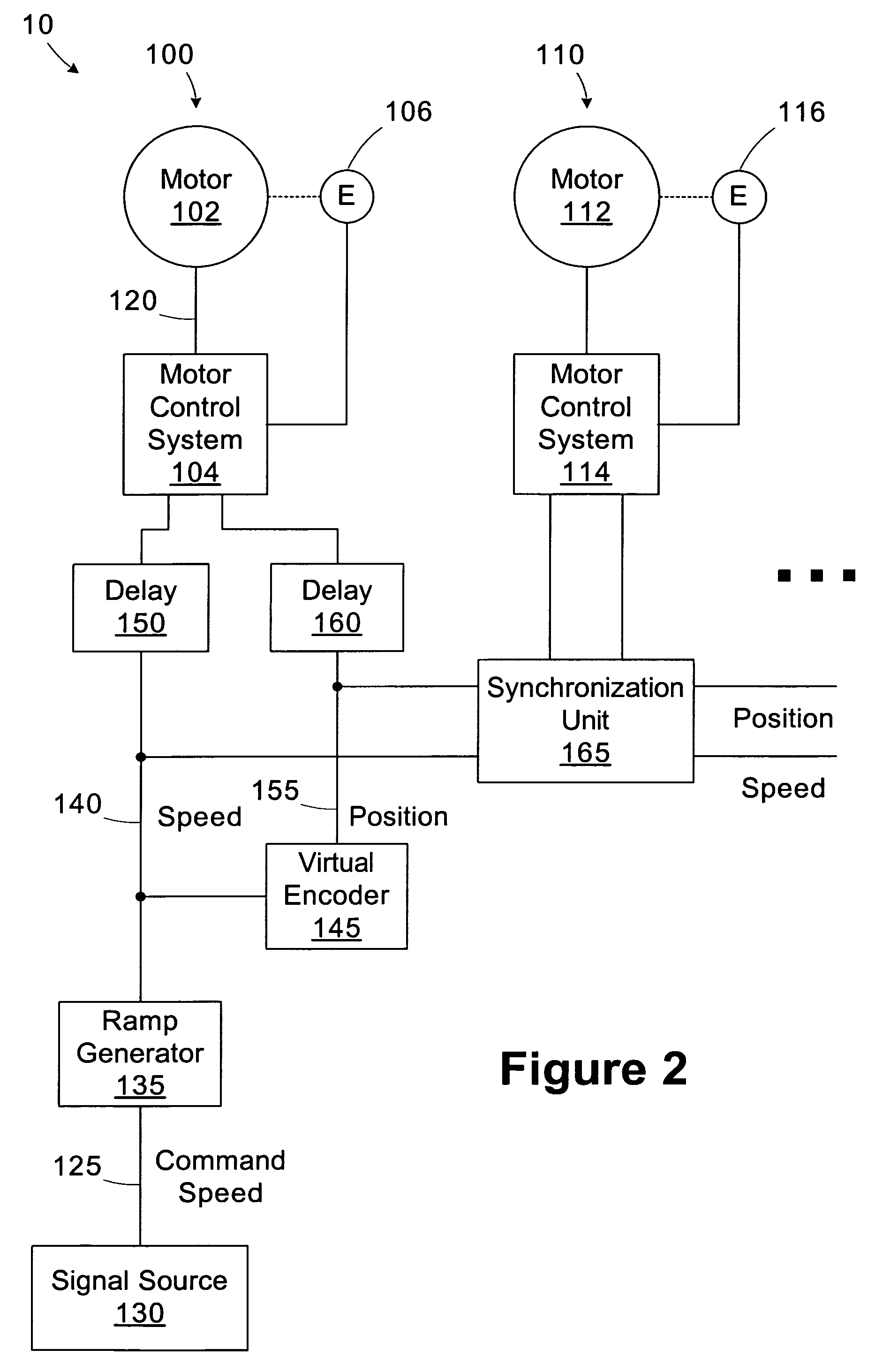
A drive unit for controlling a motor includes a position feedback device and a velocity noise filter. The position feedback device is operable to generate a position signal relating to a position of the motor. The velocity noise filter is coupled to the position feedback device and operable to filter the position signal over a predetermined number of samples to generate a velocity feedback signal for the motor.

Description

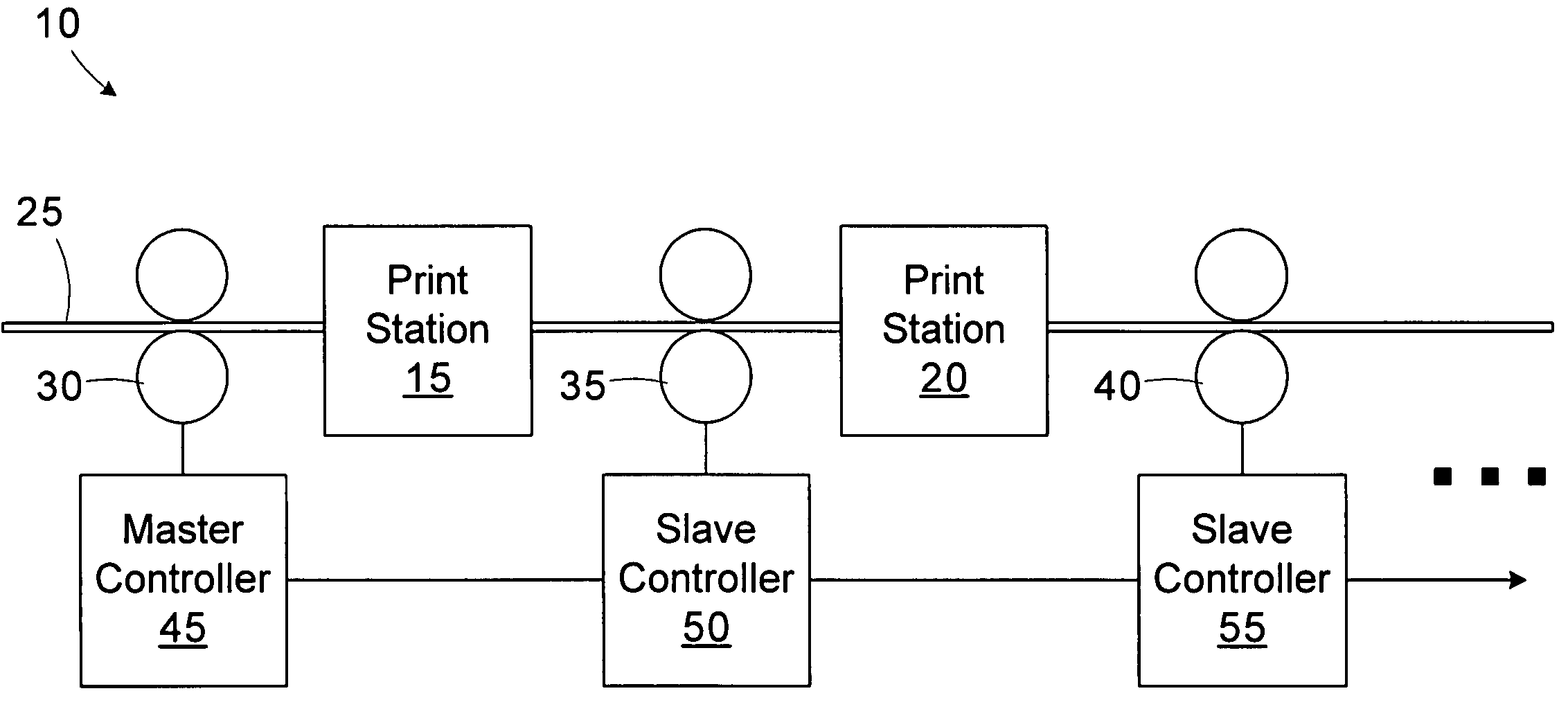
CROSS-REFERENCE TO RELATED APPLICATIONS[0001]Not applicable.STATEMENT REGARDING FEDERALLY SPONSORED RESEARCH OR DEVELOPMENT[0002]Not applicableBACKGROUND OF THE INVENTION[0003]The present invention relates generally to motor control and, more particularly, to a motor drive implementing a velocity noise filter to reduce noise susceptibility.[0004]Rotating motors are typically controlled by a motor drive that receives a reference motor velocity signal and, based on the motor velocity signal, produces and outputs a torque signal that is applied to the motor. Adjustment of the torque signal based on changes to the reference motor velocity signal relative to the feedback motor velocity ensures that the motor rotates at the reference velocity.[0005]Some applications require precise motor control across multiple, synchronized motors. For example, an electronic line system may be employed in a printing application to move the paper or other material over rollers and through various stages o...

Claims


Application Information

Patent Timeline
Patent Type & Authority Patents(United States)
IPC IPC(8): H02P5/46H02P5/00
CPCG05B19/414B41F13/0045G05B2219/41123G05B2219/41151G05B2219/41153B41P2213/734G05B2219/45187G05B2219/50216G05B2219/41423
Inventor REHM, THOMAS J.
Owner ROCKWELL AUTOMATION TECH
Why Eureka
Try Eureka