Fuser having reduced axial temperature droop

a fuser and axial temperature technology, applied in the direction of instruments, electrographic process equipment, optics, etc., can solve the problems of reducing the temperature at the end of the roller more than the central portion, affecting the smoothness of the image, so as to reduce the heat flow

Active Publication Date: 2007-03-06
LEXMARK INT INC
View PDF10 Cites 9 Cited by
  • Summary
  • Abstract
  • Description
  • Claims
  • Application Information

AI Technical Summary

Benefits of technology

[0009]In accordance with one aspect of the invention, an apparatus for fixing a toner image to a substrate is provided including a heated fusing roller. A backup member cooperates with the fusing roller to define a fusing nip. A heat control structure includes structure located adjacent a predetermined axial portion of the fusing roller and reduces the heat flow from the predetermined axial portion relative to a portion of the fusing roller outside of the predetermined axial portion.

Problems solved by technology

A common problem encountered in heating the fuser relates to a temperature difference, as measured at different axial locations along the roller, known as axial temperature droop, which may result in gloss variations of the image on the media or other problems.
In addition, convective and radiated heat energy losses may also occur at the ends of the roller, resulting in the temperature at the ends of the roller tending to decrease more than the central portion of the roller under some conditions.
The higher thermal mass roller may require a longer warm-up time from room temperature to printing temperature, and the thicker core may cause excessive temperature overshoot after completion of a print job as heat provided from the lamp during the print job continues to pass from the center of the roller to the exterior surface of the roller.
Providing a fuser roller core with a large thermal mass may result in an undesirable increase in the time for the fuser to warm up to an operating temperature.
However, one problem observed during certain conditions of operation of such a fuser roller is that the axial temperature droop may exceed a desired fuser temperature operating window.

Method used


Image

  • Fuser having reduced axial temperature droop
  • Fuser having reduced axial temperature droop
  • Fuser having reduced axial temperature droop

Examples


example 1

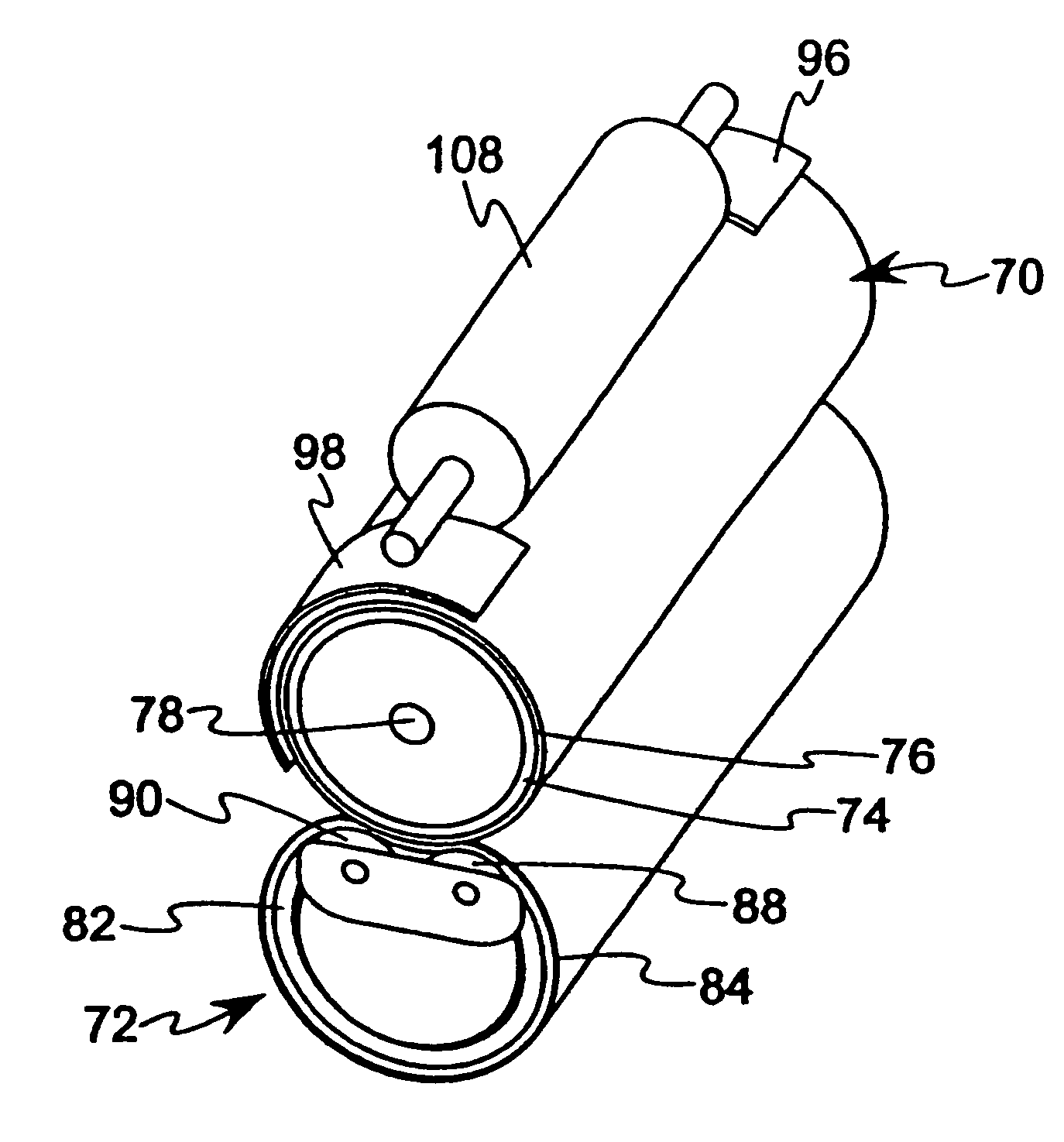
[0043]A fuser was provided including a hot roller 70 having a steel core 74 formed with an outer diameter of approximately 24.8 mm and a thickness of approximately 0.4–0.5 mm, a silicone rubber layer 76 provided over the steel core having a thickness of approximately 0.5–0.6 mm, and a PFA layer provided over the silicone rubber layer 76 having a thickness of approximately 40 microns. The length of the hot roller 70 was approximately 246 mm. The hot roller 70 was engaged with a backup member, such as the backup member 72 described above with reference to FIG. 2, to define a fixing nip between the hot roller 70 and the backup member 72. A 650 W halogen lamp 78 was located in the steel core 74, extending along the central longitudinal axis of the hot roller 70, and including a filament boosted by approximately 10% at each of the opposing ends.

[0044]Side reflectors 96, 98 were provided adjacent to the circumferential surface of the hot roller 70 adjacent each end of the hot roller 70, i...

example 2

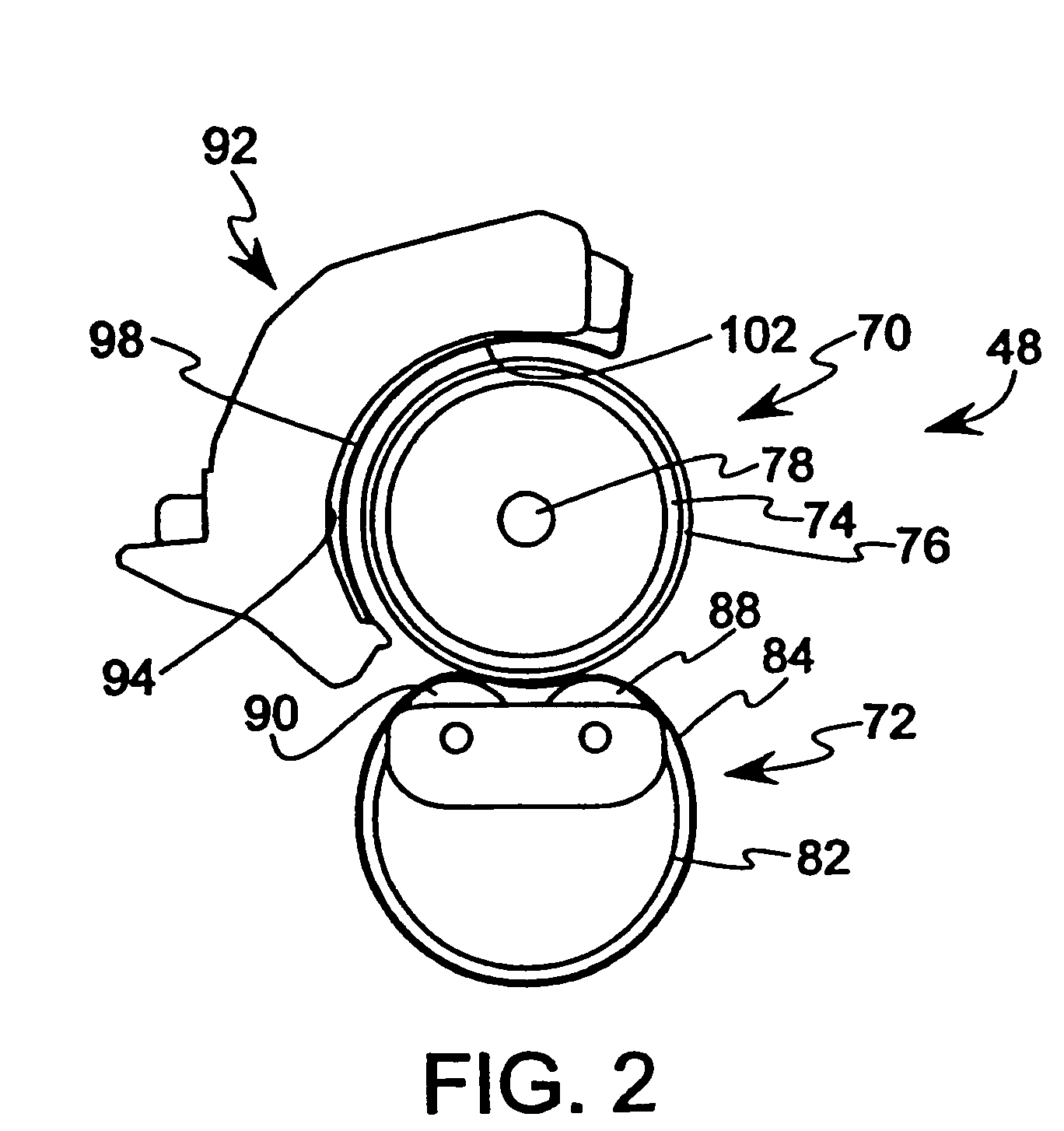
[0046]In an alternative embodiment of a fuser, a hot roller 70 and backup member 72 as described for Example 1 was provided. Side reflectors 96, 98 were provided adjacent to each end of the hot roller 70, including a gear side reflector 96 having a width of approximately 50 mm extending approximately 129° around the hot roller 70, and a non-gear side reflector 98 having a width of approximately 45 mm extending approximately 129° around the hot roller 70. The side reflectors 96, 98 were supported on an inner side 94 of a fuser cover 92 facing toward the hot roller 70. The fuser cover 92 comprised a solid cover without ventilation windows.

[0047]A steel heat absorbing roller 108, as described with reference to FIG. 4, was positioned between the side reflectors 96, 98, where the heat absorbing roller 108 was in engagement with the outer surface of the hot roller 70 during steady state operation in a standby mode in which the hot roller 70 and belt 84 were stationary. The heat absorbing ...

example 3

[0049]In a third embodiment of a fuser, a hot roller 70 and backup member 72 as described for Example 1 was provided. Side reflectors 96, 98 were provided adjacent to each end of the hot roller 70, including a gear side reflector 96 having a width of approximately 50 mm extending approximately 129° around the hot roller 70, and a non-gear side reflector 98 having a width of approximately 45 mm extending approximately 129° around the hot roller 70. The side reflectors 96, 98 were supported on an inner side 94 of a fuser cover 92′ facing toward the hot roller 70. In addition, the fuser cover 92′ included ventilation windows 110 for permitting air to pass through the cover 92′, as described with reference to FIG. 5. Specifically, a plurality of ventilation windows 110 were provided in at least a portion of the cover 92′ extending from the gear side reflector 96 toward the non-gear side reflector 98, where a portion of the cover 92′ adjacent the non-gear side reflector 98 was not provid...


PUM


Abstract

An apparatus is provided for fixing toner to a substrate including a heated fusing roller having a fusing surface. A heater element is located inside the fusing roller. A nip forming member cooperates with the fusing roller to define a fusing nip. A passive temperature control structure including a pair of members is located adjacent opposing end sections of the fusing roller, the passive temperature control structure operating to retain heat in the end sections. The passive temperature control structure may include heat reflecting members located adjacent to peripheral end portions of the hot roller to reflect heat back to the peripheral surface. In addition, the passive temperature control structure may include an end reflector facing axially toward an interior area or the hot roller for reflecting heat back to the interior of the hot roller. The temperature control structure may also comprise a heat dissipating structure including a heat absorbing roller engaged with the fusing roller or ventilation windows formed in a cover over the fusing roller.

Description

BACKGROUND OF THE INVENTION[0001]1. Field of the Invention[0002]The present invention relates to a fuser construction and, more particularly, to a method and apparatus for controlling an axial temperature distribution in a fuser.[0003]2. Related Prior Art[0004]In an electrophotographic image forming apparatus, such as a printer or copier, a latent image is formed on a light sensitive drum and developed with toner. The toner image is then transferred onto a medium, such as a sheet of paper, and is subsequently passed through a fuser where heat is applied to melt the toner and fuse it to the medium. The fuser includes a fuser roller cooperating with a backup member to form a nip through which the toned media passes. The fuser roller may be provided with an internal heater, such as a halogen lamp, and the temperature of the fuser roller is monitored by a temperature sensor providing a temperature signal for controlling the temperature of the fusing operation to a predetermined target t...

Claims


Application Information

Patent Timeline
Patent Type & Authority Patents(United States)
IPC IPC(8): G03G15/20
CPCG03G15/2017
Inventor CAO, JICHANGGILMORE, JAMES D.
Owner LEXMARK INT INC
Why Eureka
Try Eureka