Eureka AIR delivers breakthrough ideas for toughest innovation challenges, trusted by R&D personnel around the world.

Hall effect probe with exchangeable wear tips

a technology of wear tips and probes, applied in the direction of electrical/magnetic thickness measurement, semiconductor/solid-state device testing/measurement, instruments, etc., can solve the problems of time-consuming and expensive repair or replacement, and achieve the effects of reducing heat flow and thermal gradient, reducing permeability gradients, and reducing stress on concentrators

Active Publication Date: 2014-05-08
OLYMPUS NDT
View PDF5 Cites 9 Cited by
  • Summary
  • Abstract
  • Description
  • Claims
  • Application Information

AI Technical Summary

Benefits of technology

The invention relieves stress on the concentrator by using a wear tip, which improves the measured result. It also provides a consistent air gap as a thermal barrier to reduce the likelihood of permeability gradients and measuring uncertainty. The terms used in the disclosure are interchangeable, and do not limit the scope of the patent.

Problems solved by technology

The first is the use of the wear resistant, replaceable cap to prevent wear and accidental impact damage of the concentrator tip that could cause measurement inaccuracy, or require time consuming and expensive repair or replacement.

Method used


Image

  • Hall effect probe with exchangeable wear tips
  • Hall effect probe with exchangeable wear tips
  • Hall effect probe with exchangeable wear tips

Examples


Embodiment Construction

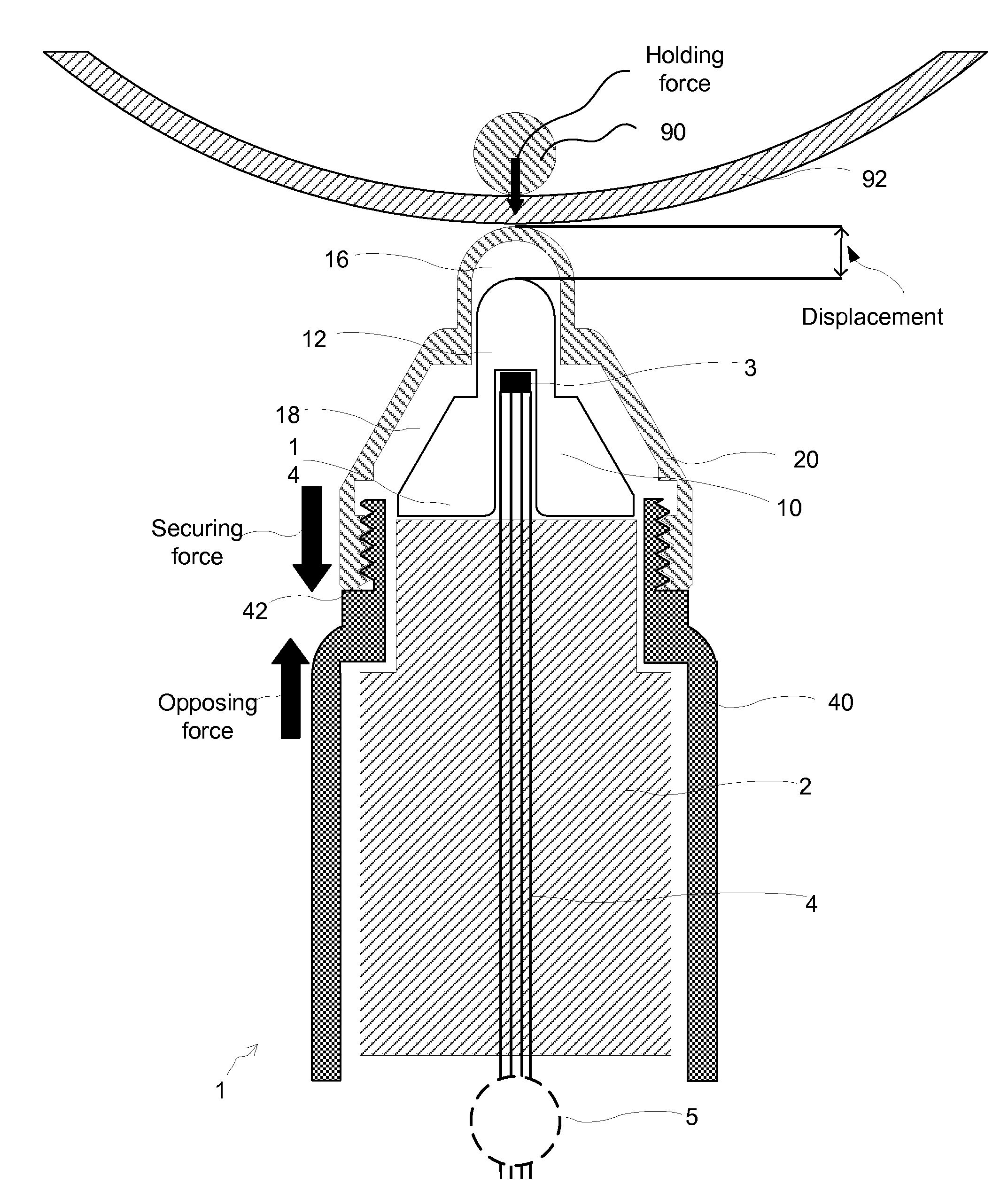
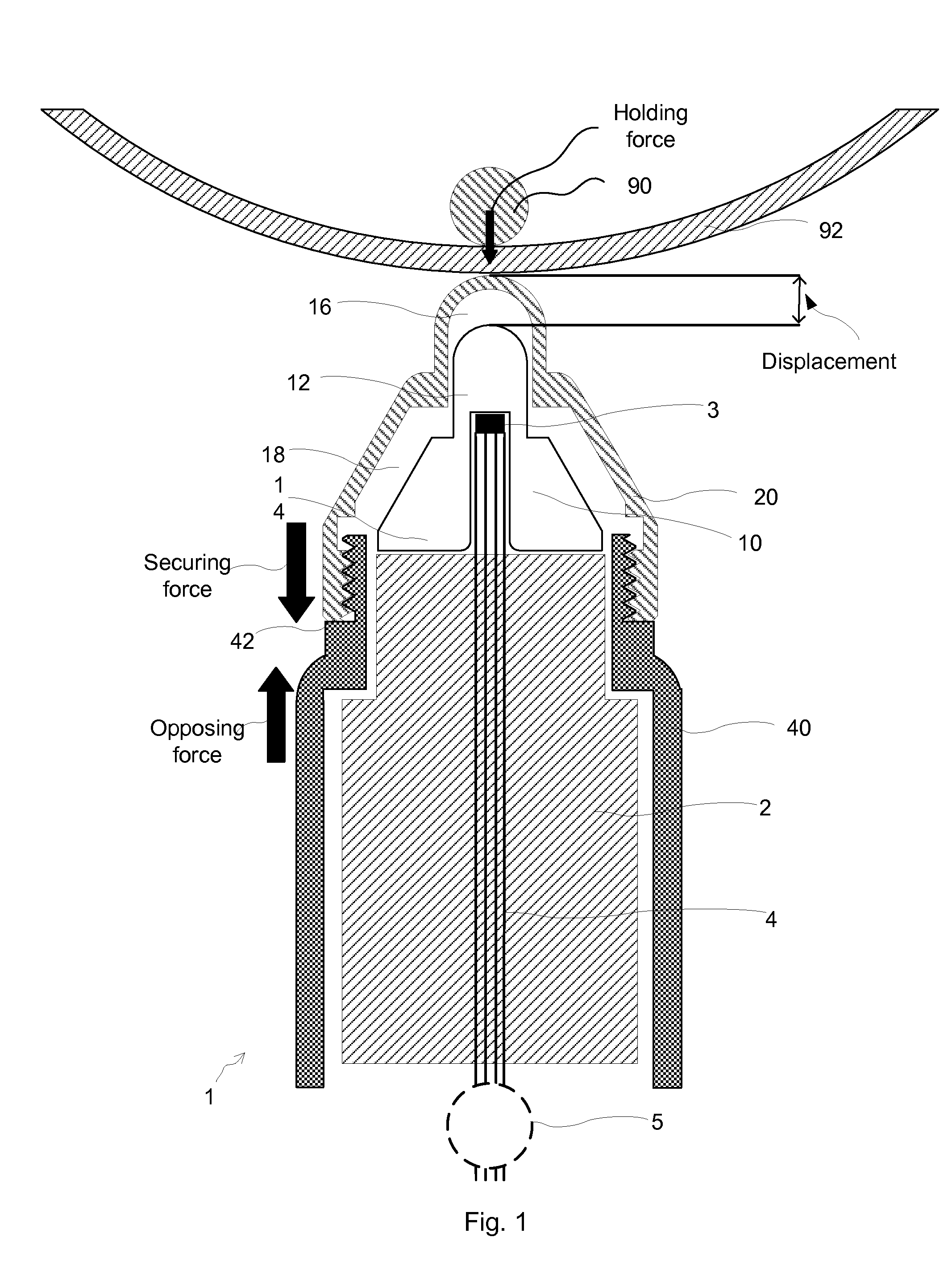
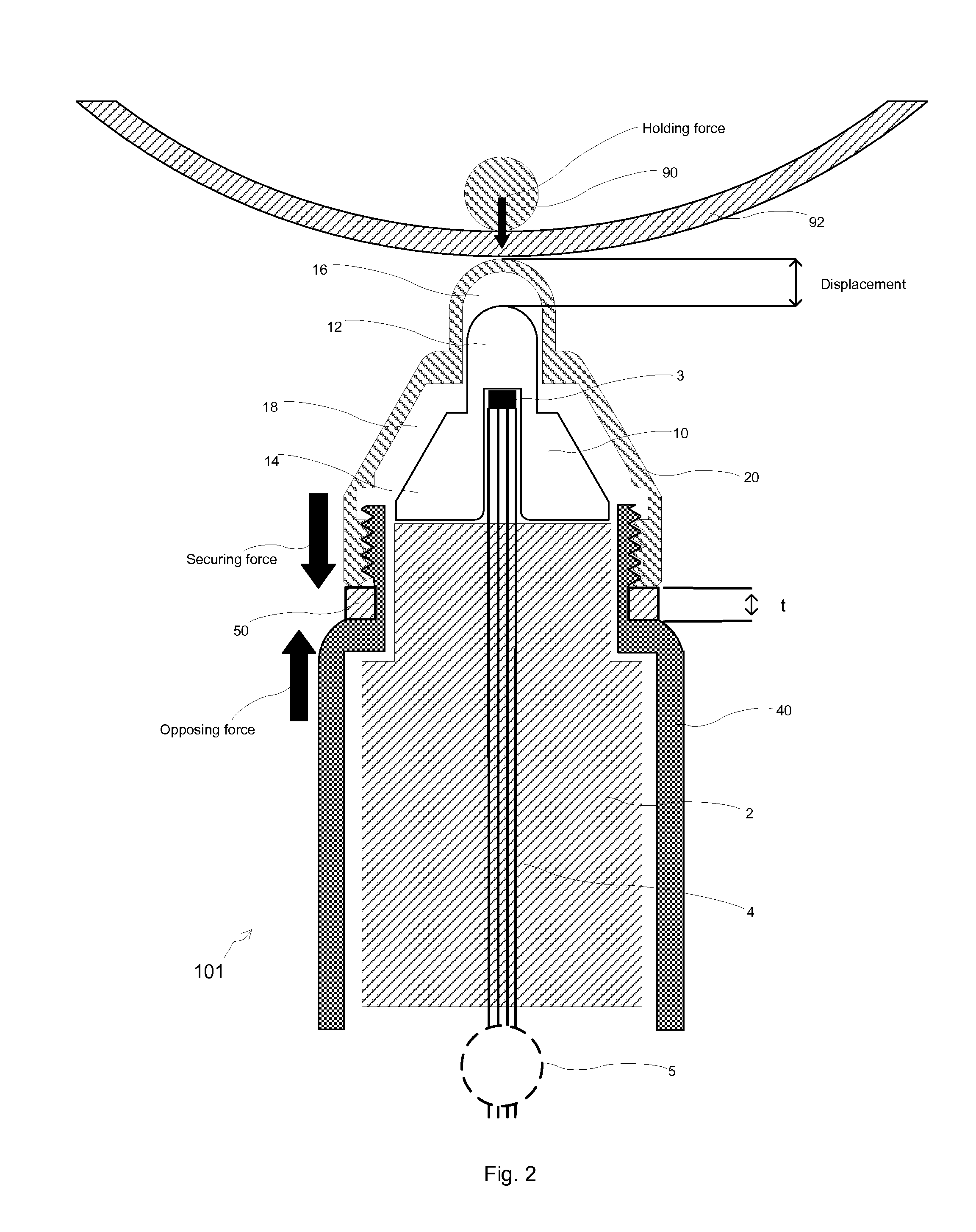
[0029]FIG. 1 shows a Hall effect probe 1 exerting a magnetic field (not shown) coupled with a magnetic target 90 for measuring the thickness of a thin wall 92 of a test object. As can be seen, during a measurement, probe 1 is placed against one side of wall 92 and target 90, with free range of movement on the other side of wall 92, is drawn to the surface of wall 92. The thickness of the wall is therefore the distance between the outer surface of target and the tip of probe 1.

[0030]The same as in existing practice, each probe can have a plurality of targets compatible and calibrated to work with each specific probe. Target(s) 90 is ferromagnetic, either being permanent with high coercivity or soft with very low remanence and is frequently in a sphere shape. It is therefore exchangeably called “target ball” in the present disclosure although other solid shapes may be used including but not limited to rods, disks, tapered disks, cylinders, ellipsoids and parallel prisms. An exemplary ...


PUM


Abstract

Disclosed is a Hall sensor probe that configured to be coupled with one of a plurality of magnetic targets for measuring the thickness of a non-ferromagnetic wall. The probe comprises a magnetic field source, a Hall sensor, a concentrator and a main housing. The novel aspects of the probe include a wear tip that is exchangeably affixed onto the main-housing, leaving a permanent gap from and disjoined from the concentrator in a manner that transfers stress from the tip directly onto the main-housing. To serve every aspects of the primary objective, being it mechanical, thermal and operational, the material of the tip preferably has a fracture toughness higher than 20 MPa·m1 / 2, wear coefficient higher than 100, and a magnetic susceptibility lower than 0.001.

Description

FIELD OF THE INVENTION[0001]The present invention relates to a thickness measurement device, more particularly to a Hall Effect probe assembly for measuring or inspecting thickness.BACKGROUND OF THE INVENTION[0002]Hall effect based electronic gauging is known to be used in thickness gauging. A typical Hall Effect probe deploys a magnetic field applied at right angles to a semiconductor element carrying a current. This combination includes a voltage in another direction perpendicular to the current flow and magnetic field. The magnetic circuit of the measurement system comprises a Hall sensor and a magnetic source such as magnets within a probe, and an external magnetic flux field. A ferromagnetic target such as a steel ball of known mass, placed in the magnetic circuit, alters the reluctance of the magnetic circuit, the magnetic flux density through the Hall sensor, and hence the induced voltage is changed. As the target is moved further away from the magnet, the magnetic reluctance...

Claims


Application Information

Patent Timeline
Patent Type & Authority Applications(United States)
IPC IPC(8): G01B7/06
CPCG01B7/06G01B7/10H01L22/12
Inventor STANTON, MATTHEW EDWARDLABRECK, STEVEN ABE
Owner OLYMPUS NDT
Why Eureka
Eureka Blog
Learn More