Eureka AIR delivers breakthrough ideas for toughest innovation challenges, trusted by R&D personnel around the world.

Fusion device divertor water cooling module and applied divertor cooling target board structure thereof

A divertor and water-cooling technology, applied in fusion reactors, thermonuclear fusion reactors, nuclear reactors, etc., can solve problems such as insufficient cooling, achieve the effects of reducing the average heat flow, increasing the total area to withstand heat flow, and eliminating the highest temperature point

Active Publication Date: 2018-10-02
XI AN JIAOTONG UNIV
View PDF7 Cites 8 Cited by
  • Summary
  • Abstract
  • Description
  • Claims
  • Application Information

AI Technical Summary

Problems solved by technology

[0010] In order to overcome the insufficient cooling of the plasma-facing surface of the existing through-tube tungsten-copper divertor, the object of the present invention is to provide a divertor water-cooled module of a fusion device and its applied divertor cooling target plate structure. In terms of structural design, the heat transfer capacity of the divertor can be directly improved. This design can more effectively disperse the energy flow from the plasma while improving the compatibility between the coolant pipeline and the surface structure facing the plasma, thereby improving the heat transfer capacity; the present invention is especially suitable for magnetic The divertor target plate of the confinement nuclear fusion tokamak device faces the plasma structure, which can improve the heat transfer performance of the cooling structure at the target plate

Method used


Image

  • Fusion device divertor water cooling module and applied divertor cooling target board structure thereof
  • Fusion device divertor water cooling module and applied divertor cooling target board structure thereof
  • Fusion device divertor water cooling module and applied divertor cooling target board structure thereof

Examples


Embodiment Construction

[0029] The present invention will be further described in detail below in conjunction with the accompanying drawings:

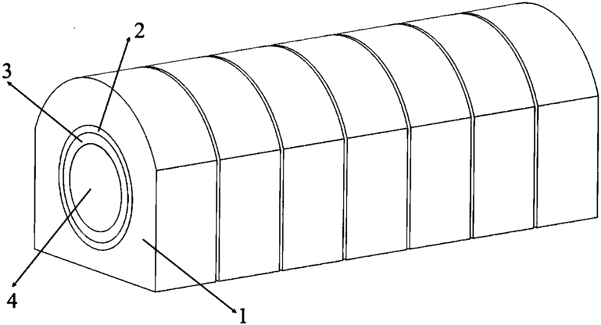
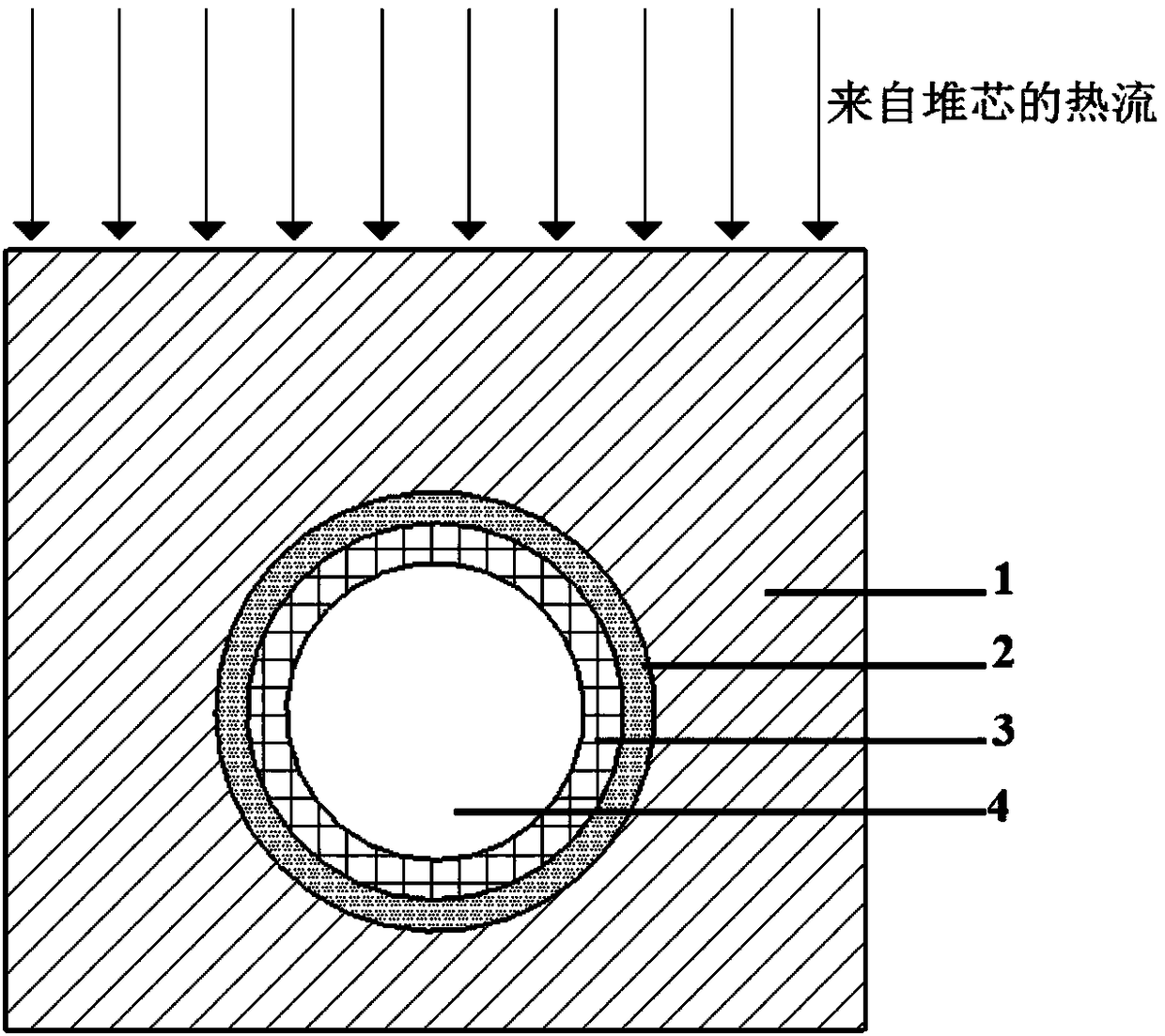
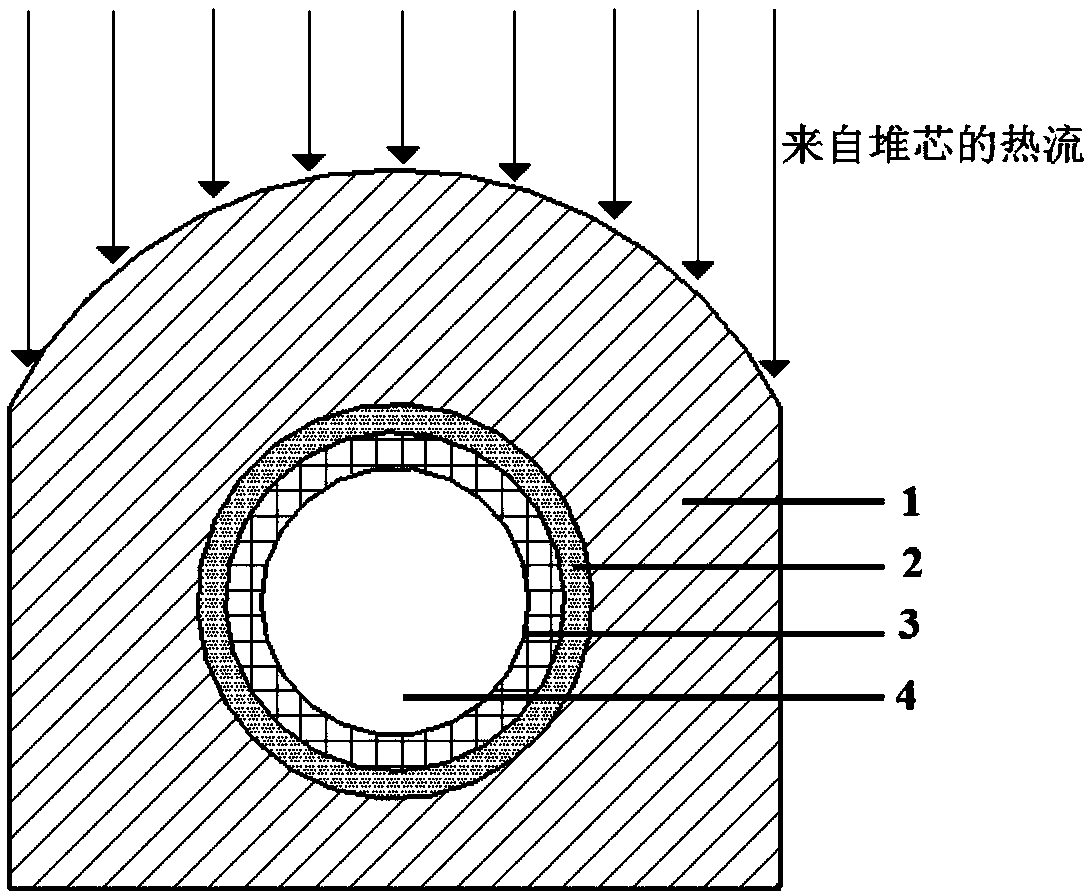
[0030] Such as figure 1 As shown, a divertor water-cooling module of a fusion device according to the present invention includes a plasma-facing structure 1 , a buffer layer structure 2 , a heat sink structure 3 and a coolant 4 . The connection between the plasma-facing structure 1, the buffer layer structure 2 and the heat sink structure 3 is hot isostatic welding. The structure is finally connected in series and then in parallel according to the axial direction of the coolant to form a whole and installed on the divertor target plate location.

[0031] Among them, the plasma-facing structure 1 is a hexahedral structure made of tungsten material, one of which protrudes in the direction of the fusion center in the shape of an arc; The component is specifically composed of a heat sink coolant pipe made of a CuCrZr alloy with high thermal conductivity; the b...


PUM


Abstract

The invention provides the structural design of a water cooling module used for cooling the divertor target board structure in a magnetic confinement nuclear fusion device. The fusion device divertorwater cooling module structure is composed of a plasma facing structure, a stress buffer layer structure welded in the plasma facing structure and a heat sink pipeline structure welded in the buffer layer structure. In the cooling structure, the coolant flows through the heat sink structure to bring away the high energy of the fusion reaction to the divertor part. The plasma facing structure is ahexahedron structure of which one surface protrudes to the fusion center direction with the heat sink pipeline and the stress buffer layer structure penetrating in the center position. The protrusionsurface structure directly bears the heat flow from the fusion center. The protrusion arc surface is coaxial with the annular stress buffer layer structure and the heat sink structure. The heat exchange capacity of the divertor can be directly enhanced from the aspect of structural design. The plasma energy flow can be more effectively dispersed by the design and the compatibility of the coolant pipeline and the plasma facing surface structure can be improved so as to enhance the heat exchange capacity.

Description

technical field [0001] The invention belongs to the technical field of magnetic confinement nuclear fusion divertor cooling, and in particular relates to a divertor water cooling module of a fusion device and a divertor cooling target plate structure applied thereto. Background technique [0002] Fusion technology is one of the ultimate ways to solve human energy problems, and this technology has been widely studied internationally. The divertor is one of the most critical devices in magnetic confinement nuclear fusion. It plays a role in the magnetic confinement tokamak device to discharge helium ash, discharge the hot flow impurity particle flow from the high temperature plasma, and prevent secondary impurities from entering the plasma again. . The part of the divertor target plate facing the plasma wall needs to withstand 10-20 MW / m from the plasma in the center of the device 2 The heat flux density, which puts forward higher requirements for the material selection and ...

Claims


Application Information

Patent Timeline
Patent Type & Authority Applications(China)
IPC IPC(8): G21B1/13G21B1/05
CPCG21B1/057G21B1/13Y02E30/10
Inventor 苏光辉赵晓晗田文喜王明军秋穗正
Owner XI AN JIAOTONG UNIV
Why Eureka
Eureka Blog
Learn More