Method for reducing heat flow rate of local reverse overflow of aircraft

A technology of aircraft and heat flow rate, applied in the direction of affecting the air flow flowing through the surface of the aircraft, aircraft parts, aircraft control, etc., can solve the problem of large drag reduction effect, and achieve the effect of reducing heat flow

Inactive Publication Date: 2012-11-28
INST OF MECHANICS - CHINESE ACAD OF SCI
View PDF5 Cites 7 Cited by
  • Summary
  • Abstract
  • Description
  • Claims
  • Application Information

AI Technical Summary

Problems solved by technology

It is found that the pressure ratio of plasma injection is under certain circumstances, although the momentum is smaller than that of cold flow injection, but the drag reduction effect is much greater than that

Method used


Image

  • Method for reducing heat flow rate of local reverse overflow of aircraft
  • Method for reducing heat flow rate of local reverse overflow of aircraft
  • Method for reducing heat flow rate of local reverse overflow of aircraft

Examples


Embodiment Construction

[0015] The reverse overflow of the present invention is a method of active cooling and heat protection, which is to overflow a normal temperature liquid, such as water, from the stagnation point of the aircraft or the surface of the predicted high heat flow area, so that it forms a thin layer in these areas, And cover the high heat flow area, thereby greatly reducing the heat flow rate on the surface of the object.

[0016] Because the protected area is narrow and the amount of liquid used is very small, there is almost no interference with the mainstream.

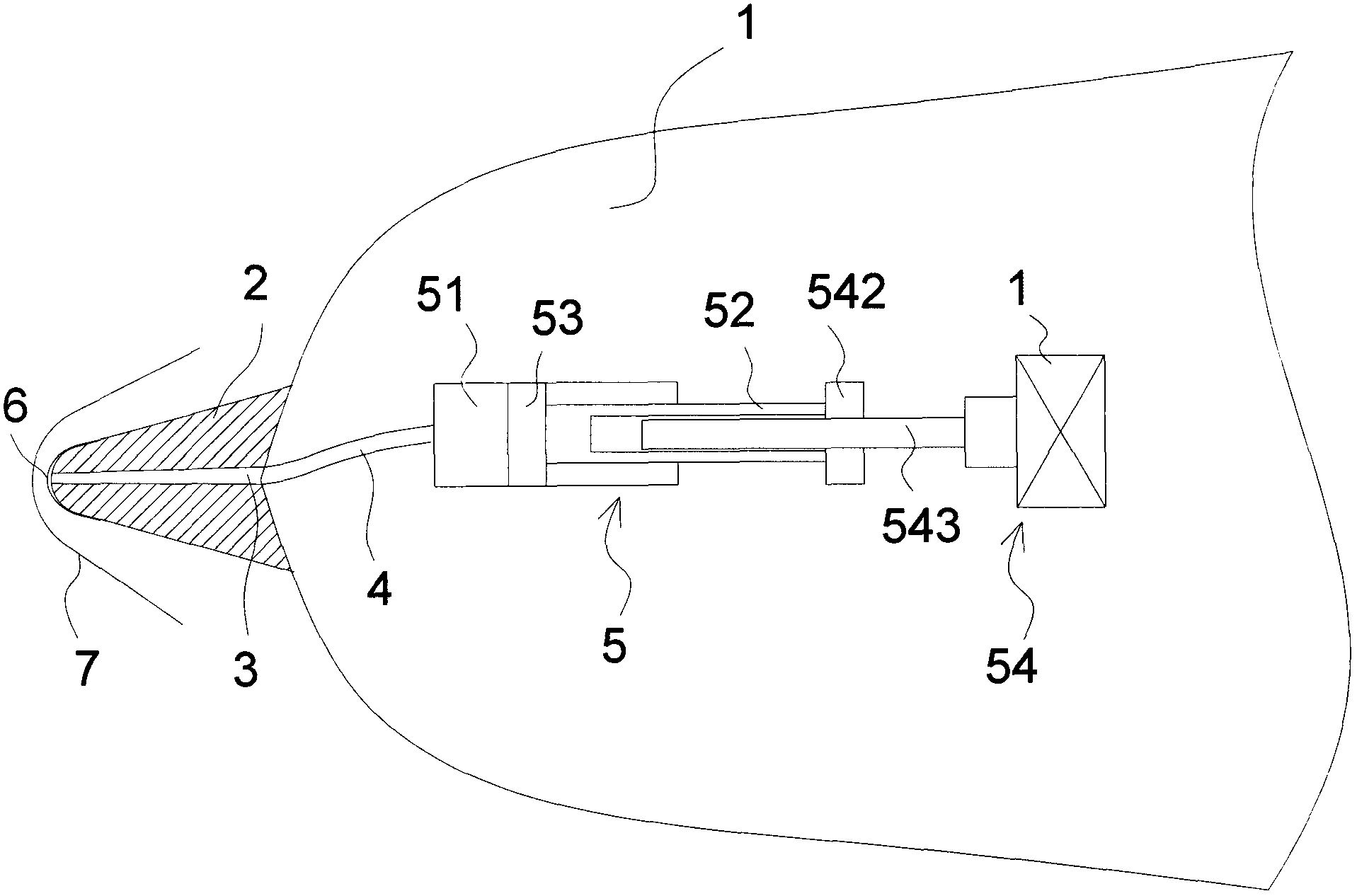
[0017] An aircraft with a large lift-to-drag ratio (such an aircraft usually has a conical head) is used as an example for illustration.

[0018] Such as figure 1 As shown, the apex position of the cone head 2 of the aircraft 1 is an area of ​​high heat flow. The tip of the cone head 2 is provided with a small hole 3, and then one end of the conduit 4 is connected to the small hole 3, and the other end is connected to a ...


PUM


Abstract

The invention discloses a method for reducing heat flow rate of local reverse overflow of an aircraft. The method comprises that normal temperature liquid overflows from the surface of a local high heat flow zone of the aircraft, and the liquid forms a thin layer on the high heat flow zone to cover the surface of the local high heat flow zone of the aircraft, so that the heat flow rate of the surface of the local high heat flow zone is reduced. According to the method, the normal temperature liquid continually overflows the surface of the local high heat flow zone of the aircraft, and under the condition that the aircraft flies at a high speed, the liquid forms the thin layer on the surface of the local high heat flow zone; the flow quantity of the overflowing liquid is a little, the area of the thin layer formed on the surface is small, and the thin layer mainly covers the local high heat flow zone, so the main flow of the aircraft is almost not disturbed, and the continual overflow can play a good role in reducing the heat flow of the local high heat flow zone. The method is particularly suitable for the sharp conical head of the aircraft with high lift-drag ratio.

Description

technical field [0001] The invention relates to a method for reducing heat flow rate by partial reverse overflow of an aircraft. Background technique [0002] The earliest studies on flood cooling were tangential jets to form a film to reduce the heat flow. In 1946, Wieghardt conducted research on hot air deicing to solve the problem of wing icing. In 1966, Goldstein et al first carried out experimental research on tangential sonic jet flow in Ma=3 supersonic flow. In 1970, Parthasarthy and Zakkay performed an experimental study on the near-tangential injection of different refrigerants (helium, hydrogen and argon) in the mainstream of Ma=6. From 1970 to 1971, Cary and Hefner conducted experimental research on flat film cooling in the mainstream of Ma=6, and the refrigerant was air. [0003] Their research found that the film cooling effect of Ma=6 supersonic flow is significantly higher than that of subsonic and Ma<6 supersonic flow under the same injection structure,...

Claims


Application Information

Patent Timeline
IPC IPC(8): B64C23/00
Inventor 俞鸿儒陈宏陈兵
Owner INST OF MECHANICS - CHINESE ACAD OF SCI
Why Eureka
Try Eureka