Thermally compensated test piece for coordinate measuring machines

a technology of coordinate measuring machine and test piece, which is applied in the field of test piece, can solve the problems of limiting material choices, affecting the quality of the test piece, and the cost of production of special materials with negative thermal expansion coefficients, etc., and achieves the effect of simple positioning

Inactive Publication Date: 2007-03-13
METRONOM
View PDF15 Cites 11 Cited by
  • Summary
  • Abstract
  • Description
  • Claims
  • Application Information

AI Technical Summary

Benefits of technology

[0010]The advantage of such a test piece is that the length variations of the shaped probe elements and / or the connecting elements is compensated by the fastening elements. Thus in particular a high accuracy in the checking of coordinate measuring machines is obtained. Furthermore, the material and / or the dimensioning of the shaped probe elements and the connecting elements can largely be chosen free. If an expensive material with a negative thermal expansion coefficient is chosen, the required amount of material is considerably less as if the complete connecting element would have to be made thereof. Therefore, the inventive test piece results in a substantially higher flexibility for the choices of the materials and / or the dimensioning; additionally the production costs can be reduced.
[0024]According to an advantageous development of this test piece the connecting elements form the edges and the shaped probe elements form the corners of a tetrahedron, as shown in FIG. 3. Such a test piece geometry permits a simple positioning. Furthermore, due to the tetrahedron form all shaped probe elements are accessible with just a single sensing pin.

Problems solved by technology

A first disadvantage of the mentioned prior art is, that the material and / or the dimensioning of the complete connecting elements have to be chosen such that the expansions or contractions of the shaped probe elements are compensated.
Thus, one is strongly restricted in the choices of the material and in particular in the dimensioning of the connecting elements.
A further disadvantage is that special materials with negative thermal expansion coefficients are generally more expensive to produce, from which a high price of the test element results.

Method used


Image

  • Thermally compensated test piece for coordinate measuring machines
  • Thermally compensated test piece for coordinate measuring machines
  • Thermally compensated test piece for coordinate measuring machines

Examples


Embodiment Construction

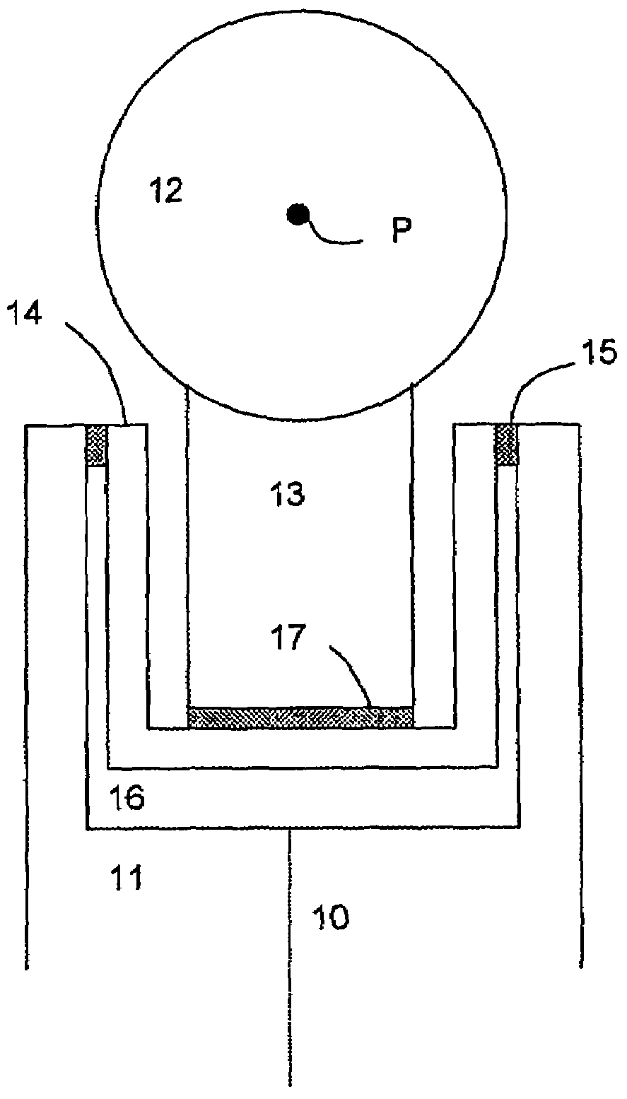
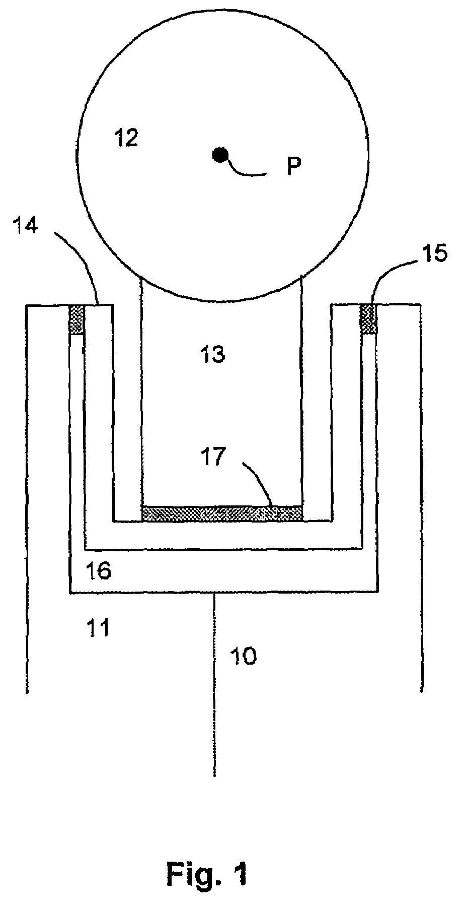
[0029]FIG. 1 shows a fastening element which is embedded in the connecting element 11. For this purpose the end of the connecting element 11 has been hollowed out, such that a cavity 16 is formed. Alternatively the complete connecting element can be hollow. The fastening element comprises a hollow body in the form of a sleeve 14, as a first sectional element, which at the upper rim is adhesively bonded at a location 15 to the inside of the connecting element 11. This connection can be arranged either only at several punctual locations or for example around the complete sleeve in a narrow region at the upper rim. The less the adhesively bonded area is, the less tensions occur during contractions and dilations. Within the sleeve 14 is a second sectional element 13, on which the ball-shaped probe element 12 with sensing point P is arranged. At its base the sectional element 13 is adhesively bonded to the bottom of the sleeve. This can be effected via the layer 17 or only at single poin...


PUM


Abstract

Test piece, comprising at least two shaped probe elements and at least one connecting element for connecting the at least two shaped probe elements. Each connecting element is provided with at least one fastening element at one end of the connecting element for fastening a shaped probe element. Length variations of the at least two shaped probe elements and / or of the at least one connecting element are compensated by the fastening elements in such a way that the distance between respective two sensing points under standard measuring conditions is essentially constant.

Description

FIELD OF THE INVENTION[0001]The invention relates to a test piece with at least two shaped probe elements and with at least one connecting element for connecting the at least two shaped probe elements, wherein each connecting element is provided with at least one fastening element for fastening a shaped probe element to an end of the connecting element.BACKGROUND OF THE INVENTION[0002]Such a test piece is known from DE 199 15 012.[0003]Test pieces serve in general for the adjustment and the surveillance of specially positioning and measuring systems, in particular of mobile coordinate measuring systems. They customary consist of reference elements, so called shaped probe elements, which are connected by connecting elements and which have accurately defined distances from each other. A coordinate measuring system is checked by determining the relative positions of the shaped probe elements. The relative positions obtained in that way are compared with the actual distances of the test...

Claims


Application Information

Patent Timeline
Patent Type & Authority Patents(United States)
IPC IPC(8): G01B5/00G01B3/30G01B1/00G01B21/04
CPCG01B21/042G01B1/00
Inventor BLONDEAU, JEAN
Owner METRONOM
Why Eureka
Try Eureka