Multi-stage diffuser nozzle

a diffuser and multi-stage technology, applied in the direction of drilling machines, cutting machines, constructions, etc., can solve the problems of premature failure of the rock bit, excessive erosion of the cone shell and other components, and unusable recirculation paths, so as to improve the penetration rate of the drill bit and improve the cleaning effect of the cone shell

Inactive Publication Date: 2007-03-13
SMITH INT INC
View PDF32 Cites 27 Cited by
  • Summary
  • Abstract
  • Description
  • Claims
  • Application Information

AI Technical Summary

Benefits of technology

[0014]Another aspect of the invention is a drill bit with a center multi-stage diffuser nozzle and diverging nozzles installed at non-central por

Problems solved by technology

Too much drilling fluid exiting the peripheral jets is believed to encourage undesirable re-circulation paths for drilling fluid at the bottom of the wellbore.
However, due to erosion concerns typically only 15 to 30 percent of the total hydraulic fluid (drilling fluid or drilling mud) flow passes through the center jet, with the remainder of the mud being jetted through the peripheral nozzles.
In particular, excessive drilling fluid flow through the center jet causes flow erosion at the cutter surfaces such as the tips of the cutting teeth, resulting in premature failure of the rock b

Method used


Image

  • Multi-stage diffuser nozzle
  • Multi-stage diffuser nozzle
  • Multi-stage diffuser nozzle

Examples


Embodiment Construction

[0046]With reference now to FIG. 1, rotary cone rock bit generally designated as 10 consists of rock bit body 12, pin (upper) end 14 and cutting (lower) end generally designated as 16. A fluid chamber or plenum 13 is formed within bit body 12. The plenum 13 communicates with open pin end 14. Drill bit fluid or “mud” enters the bit body through the pin 14 via a drill pipe attached to the pin (not shown). A dome portion 17 defines a portion of the plenum 13 within body 12. Rock bit legs 20 extend from bit body 12 toward the cutting end 16 of the bit. A cutter cone 18 is rotatably fixed to leg 20 through a journal bearing extending into the cone from the leg backface 22 of the leg 20 (not shown).

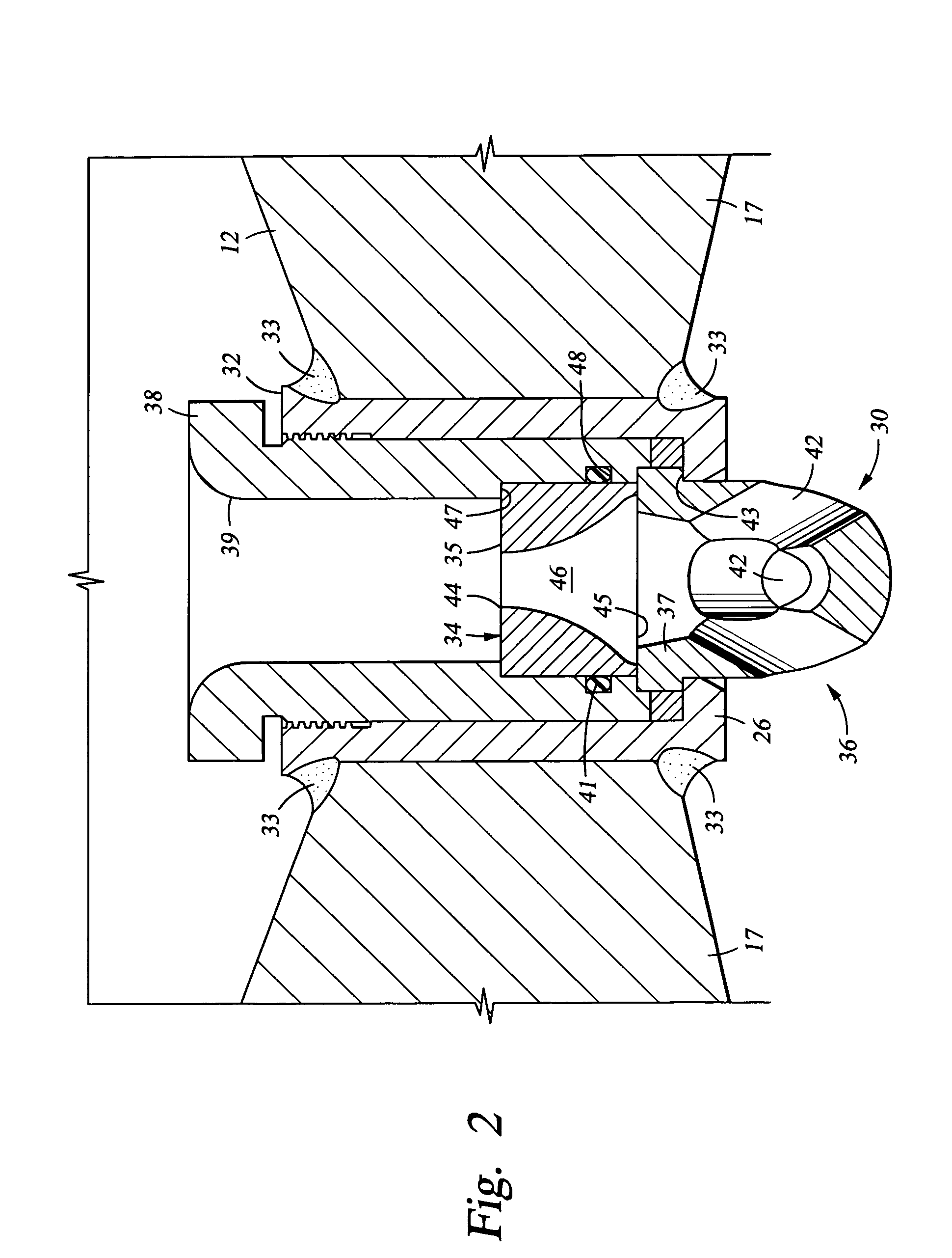
[0047]Also shown is a multi-stage diffuser nozzle 30 according to a first embodiment of the invention. The multi-stage diffuser nozzle 30 of FIG. 1 generally includes two components, an upper flow restrictor 34 stacked on top of a lower fluidic distributor 36. Fluidic distributor 36 and flow re...


PUM


Abstract

A multi-stage diffuser nozzle for use as a drill bit nozzle jet includes a flow restriction portion upstream of a fluidic distributor portion, and also preferably includes a transition region between these two. The flow restrictor communicates with the interior fluid plenum of a drill bit and is used to limit or restrict the total flow of drilling fluid by having a relatively small cross-sectional area for fluid flow. The fluidic distributor communicates with the flow restrictor and reduces the exit flow velocities of the drilling fluid as the drilling fluid is ejected from the nozzle by providing a relatively larger cross-sectional area for fluid flow. The fluidic distributor also directs the flow paths of the drilling fluid to locations such as cone surfaces that are prone to bit balling. The transition region is an area that dampens fluid pressure oscillations in the drilling fluid.

Description

CROSS-REFERENCE TO RELATED APPLICATIONS[0001]This is a Continuation-In-Part application of co-pending U.S. patent application Ser. No. 09 / 736,613, filed Dec. 14, 2000, which issued as U.S. Pat. No. 6,585,063.STATEMENT REGARDING FEDERALLY SPONSORED RESEARCH OR DEVELOPMENT[0002]Not Applicable.BACKGROUND OF THE INVENTION[0003]Nozzle jets have been used for several years in rotary cone rock bits both in or near the center of the rock bit and around the peripheral edge of the bit to encourage cone cleaning, to enhance removal of debris from a borehole bottom, and to efficiently cool the face of the rock bit.[0004]Rotary cone rock bits are typically configured with multiple jet nozzle exits spaced at regular intervals along the periphery of the bit. High velocity fluid from these jet nozzles impacts the hole bottom and removes rock cuttings and debris. Center jets are also used in rotary cone rock bits for a variety of reasons. These include enhanced cone cleaning, protection against bit ...

Claims


Application Information

Patent Timeline
IPC IPC(8): E21B7/00E21B10/18E21B10/60E21B10/61
CPCE21B10/18E21B10/61
Inventor LARSEN, JAMES L.GABRIEL, GODWIN APEHSIRACKI, MICHAEL A.TERRACINA, DWAYNE P.
Owner SMITH INT INC
Why Eureka
Try Eureka