Projection optical system

a projection optical system and optical system technology, applied in the field of reflection lighting optical system, can solve the problems of increasing manufacturing costs, blurred vision, and incurred astigmatism, and achieve the effects of reducing the depth of a whole, preventing astigmatism, and improving lighting efficiency

Inactive Publication Date: 2007-03-13
LG ELECTRONICS INC
View PDF12 Cites 4 Cited by
  • Summary
  • Abstract
  • Description
  • Claims
  • Application Information

AI Technical Summary

Benefits of technology

[0059]An object of the present invention is to provide a reflective lighting optical system that can prevent astigmatism and improve lighting efficiency by allowing red, green and blue signals reflected on an LCoS panel to be incident to a projection lens without passing through a wire grid type PBS.
[0060]Another object of the present invention is to provide a reflective lighting system that can minimize a depth of a whole optical system using a film-type optical component such as a wire grid type PBS by minimizing a back focus length of a projection lens.
[0061]Still another object of the present invention is to provide an optical system that uses a wire grid type PBS for a lighting system, not affecting an optical performance and minimizing a height of the system.

Problems solved by technology

However, four color selectors and four PBSs are required, increasing the manufacturing costs.
Furthermore, in the course of the P / S separation / synthesize process by the PBS, there may be a photoelasticity problem causing the incident wave to have a different ray of polarized light when the incident wave is outputted.
However, an astigmatism problem is incurred.
That is, when the glass plate is inserted in the imaging lens system at an oblique angle, astigmatism that prevents light rays from focusing clearly at one point on the retina, resulting in blurred vision, is generated.
That is, as shown in the drawings, there is a problems that astigmatism is incurred when the light ray passes through the wire grid type PBS inserted between the projection lens and the LCoS panel at the oblique angle.
As described above, the conventional reflective lighting systems have a variety of problems.
That is, the reflective lighting system of the 3-PBS system as illustrated in FIG. 1 has problems that the depth of the system is increased due to the three light path portions and a number of components are required.
Although the reflective lighting system of the color quad system as illustrated in FIG. 2 has an advantage of a simplified structure due to the two light path portions, it has a problem that the manufacturing cost is increased due to the four color selectors and the four PBS.
Furthermore, in the course of the P / S separation / synthesize process by the PBS, there may be a photoelasticity problem causing the incident wave to have a different ray of polarized light when the incident wave is outputted.
Although the reflective lighting systems each using the wire grid type as illustrated in FIGS. 3 and 4 solve the problems such as the photoelasticity problem, the cost problem and the lighting efficiency problem, it has an astigmatism problem.
However, when the thickness of the PBS is reduced, the glass plate may be deformed.
In addition, even when the PBSs are disposed in a different direction, the astigmatism is not compensated for, but a shape of a spot is formed in a circular-shape, increasing the size of the spot.
Furthermore, since the PBSs have a different angle from each other, the lighting system cannot be structured on a single plane.

Method used


Image

  • Projection optical system
  • Projection optical system
  • Projection optical system

Examples


second embodiment

[0099]To solve the aforementioned drawback, a structure of FIG. 13 according to the present invention is provided.

first embodiment

[0100]The reflective lighting optical system of FIG. 13 is identical to that of the first embodiment except that it is elected with LCoS panels rotated by 90°.

[0101]However, the structure of FIG. 13 may also have a drawback that the depth of the optical system is increased and thereby the depth of the actual TV set is increased.

[0102]To solve the aforementioned drawback, a structure of FIG. 14 is provided.

third embodiment

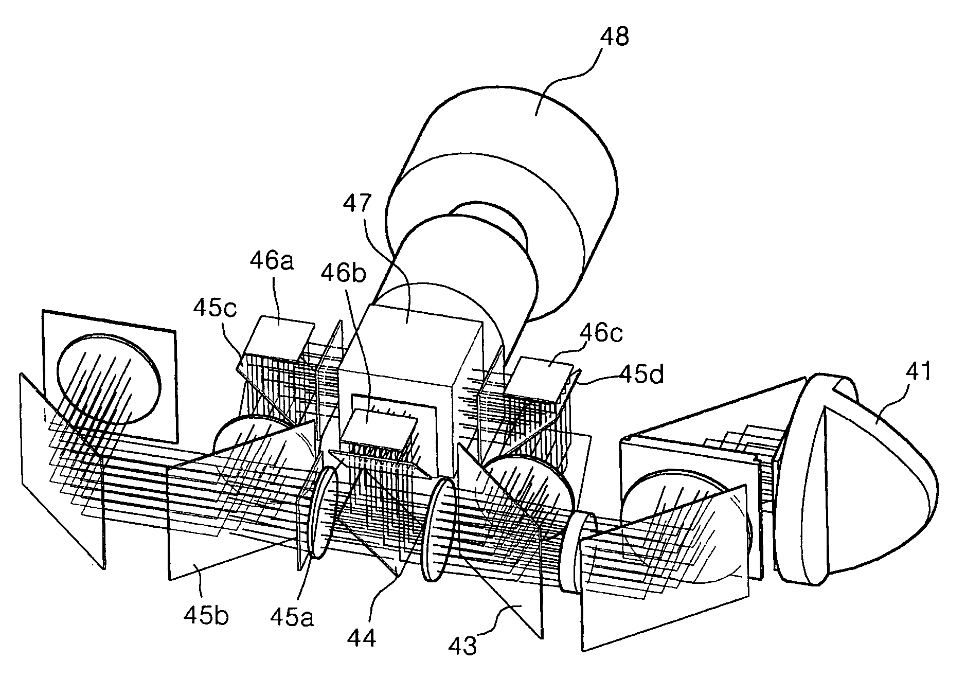
[0103]FIG. 14 illustrates a reflective lighting optical system according to the present invention.

[0104]FIGS. 15 and 16 respectively illustrate lower and upper light path portions of a reflective lighting optical system depicted in FIG. 14, and FIG. 17 illustrates a diagram viewed in front of a projection lens of a reflective lighting optical system depicted in FIG. 14.

[0105]A lighting optical system according to this embodiment of the present invention has a structure where a film type wire grid type PBS is used. At this time, in order to prevent astigmatism from being generated, light rays of R, G and B that are incident to the projection lens do not pass through the wire grid type PBS but are reflected and then incident to the X-prism.

[0106]Also, the lighting optical system has the structure to solve contrast lowering and light amount lowering problems due to the conventional photoelasticity of the PBS by using a polarization film providing the same function as the conventional P...


PUM

PropertyMeasurementUnit
phaseaaaaaaaaaa
oblique angleaaaaaaaaaa
areaaaaaaaaaaa

Abstract

A reflective lighting optical system minimizes a back focusing distance and a depth of the system, and improves a lighting efficiency by disposing a wire grid type PBS (Polarized Beam Splitter) at an oblique angle with respect to a short side of an imager.

Description

[0001]This Non-provisional application claims priority under 35 U.S.C. § 119(a) on Patent Application No(s). 10-2003-30674 filed in Korea on May 14, 2003, the entire contents of which are hereby incorporated by reference.BACKGROUND OF THE INVENTION[0002]1. Field of the Invention[0003]The present invention relates to a reflective lighting optical system, and more particularly, to a reflective lighting optical system that can minimize a back focusing distance and a height of the system, and improve a lighting efficiency by disposing a wire grid type PBS (Polarized Beam Splitter) at an oblique angle with respect to a short side of an imager.[0004]2. Description of the Related Art[0005]Recently, it has become a general tendency that a display device is designed to be slim and lightweight while having a large-sized screen. Particularly, the realization of the display device having such a large-sized screen becomes a major task in the display field. To date, a projection TV is well known ...

Claims


Application Information

Patent Timeline
Patent Type & Authority Patents(United States)
IPC IPC(8): G03B21/14G02F1/13G02B27/18G02F1/1335H04N5/74H04N9/31
CPCG03B21/14G03B21/005G03B33/12H04N5/74
Inventor KANG, HO JOONG
Owner LG ELECTRONICS INC
Why Eureka
Try Eureka