
Electrical connection box

a technology of electrical connection and box body, which is applied in the direction of connection contact material, electrical apparatus casing/cabinet/drawer, coupling device connection, etc., and can solve problems such as short circuits

Active Publication Date: 2007-03-13
AUTONETWORKS TECH LTD +2
View PDF8 Cites 23 Cited by
  • Summary
  • Abstract
  • Description
  • Claims
  • Application Information

AI Technical Summary

Benefits of technology

The present invention aims to prevent short circuits between bus bars caused by raindrops that may enter the fuse box of an electric connection box. The invention includes a water-discharge channel that removes water from the fuse box to the outside of the electrical connection box, reducing the likelihood of short circuits. Additionally, the invention includes a fuse box that is located at the upper part of the circuit housing, which further prevents short circuits between bus bars.

Problems solved by technology

At this time, when raindrops remain on the upper face of the casing, there is a possibility that a short circuit may occur between bus bars, which requires for improvement.

Method used


Image

  • Electrical connection box
  • Electrical connection box
  • Electrical connection box

Examples


Embodiment Construction

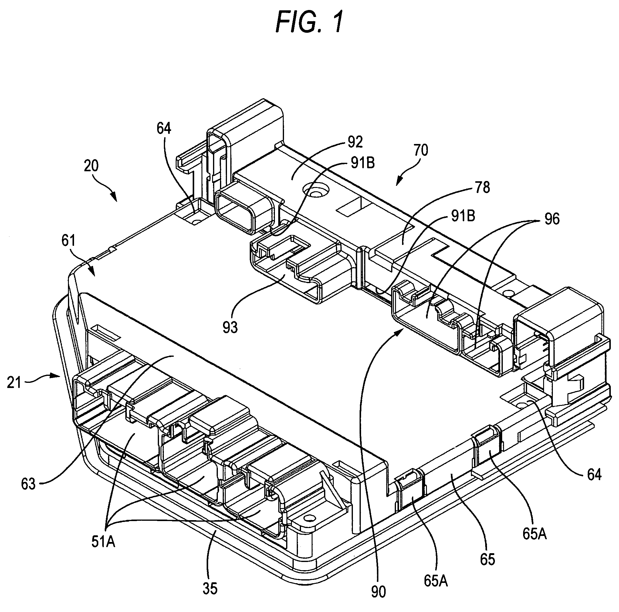
[0020]An embodiment of the present invention will be explained with reference to FIGS. 1–9.

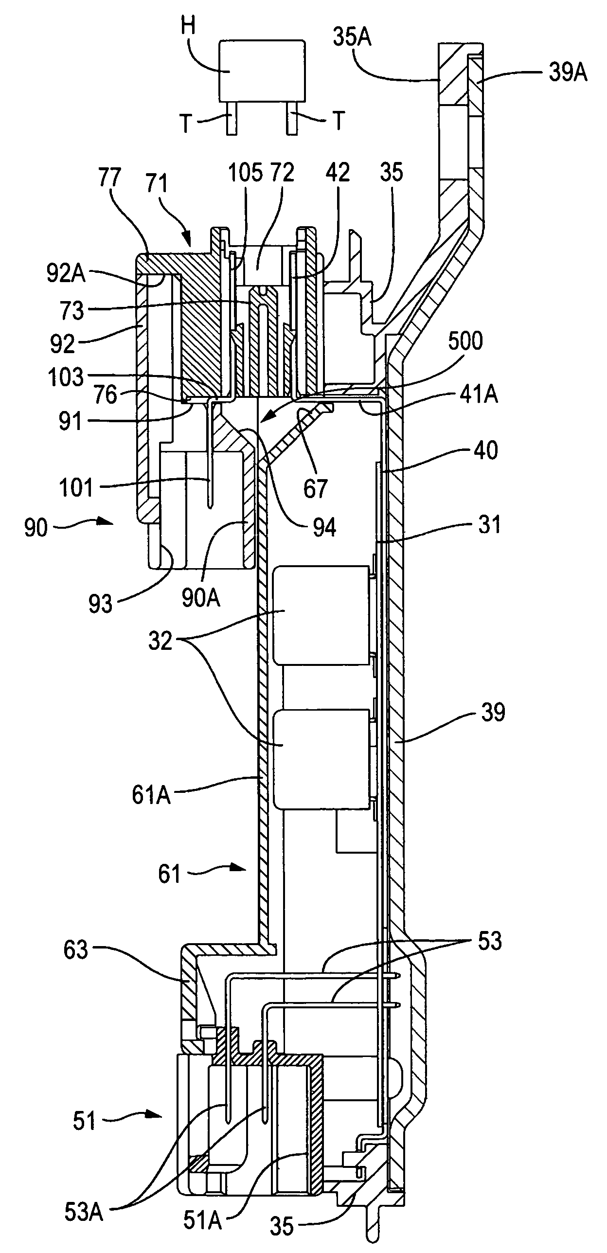
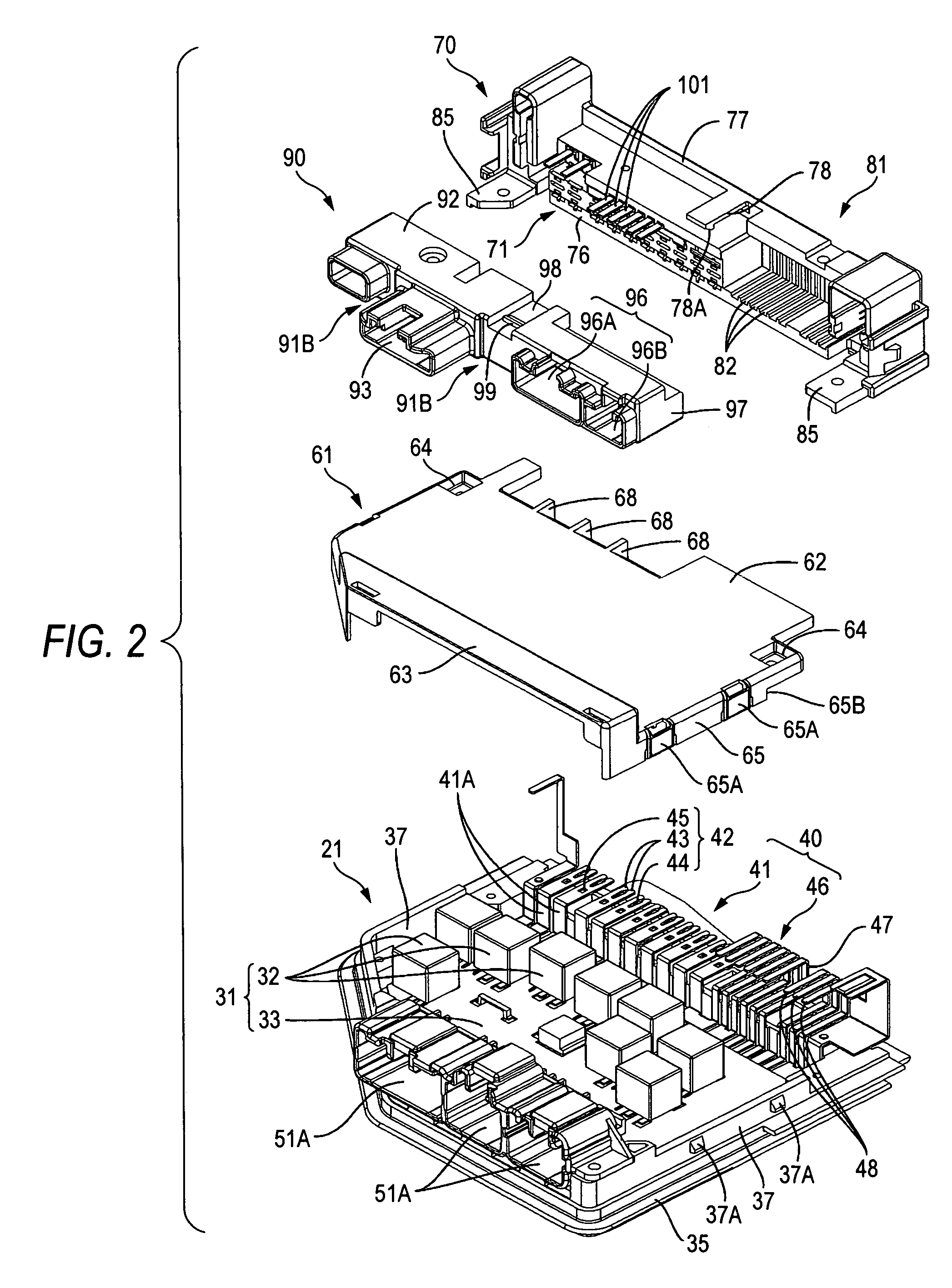
[0021]A member 20 shown in FIG. 1 is an electrical connection box used in an automobile and provided between a power source such as a battery and an electrical load (electrical components such as lamps and audio products), by which electric power supplied from the power source is distributed and supplied to individual electrical components and also control is performed such as switching of the power supply. The electrical connection box 20 is formed mainly with the body of the connection box 21 for accommodating therein the circuit component 31 in which electrical components 32 such as switching elements being mounted on the circuit substrate 33, the lower connector 51, the fuse box 70, the upper connector 90 (corresponding to the connector housing of the present invention), and it is disposed, for example, inside an engine compartment vertically.

[0022]In the following description, the vertica...


PUM


Abstract

An electrical connection box is to be attached to an attachment objective member. The electrical connection box includes: a circuit housing that accommodates a circuit substrate; a fuse box that detachably accommodates a fuse element, the fuse box being provided at an upper portion of the circuit housing in a state where the electrical connection box being attached to the attachment objective member; a plurality of bus bars that connect the circuit substrate and the fuse element; and a water-discharge channel that discharges water flowed into the fuse box to outside of the electrical connection box, the water-discharge channel being provided at a lower part of the bus bars in a state where the electrical connection box is attached to the attachment objective member, and at a position between the circuit housing and the fuse box.

Description

BACKGROUND OF THE INVENTION[0001]1. Field of the Invention[0002]The present invention relates to an electrical connection box mounted mainly in an automobile.[0003]2. Description of the Related Art[0004]An electrical connection box mounted in an automobile has been so far installed in an engine compartment and others, depending on the case. Thus, measures have been taken for preventing a short circuit between circuit substrates or between bus bars, due to immersion of water used in washing an automobile (See JP-A-2003-348732).[0005]In the conventional electrical connection box, a fixing part for connecting an external connector is integrally provided on an upper face of a frame for accommodating the circuit substrate. The fixing part is provided with a terminal-accommodating hole, which penetrates vertically, in which a terminal having an external connector and a terminal (bus bar) for connecting the circuit substrate part accommodated. Therefore, there is a possibility that water c...

Claims


Application Information

Patent Timeline
Patent Type & Authority Patents(United States)
IPC IPC(8): H05K1/00B60R16/02H01H85/20H01R9/24H01R13/52H01R13/68H02G3/16H05K5/00
CPCH01R9/245H05K7/026H01R13/5227Y10S439/949
Inventor FUKUSHIMA, HAYATOYAMANE, SHIGEKITOMIKAWA, TADASHIKAWAKITA, SHINJI
Owner AUTONETWORKS TECH LTD
Learn More