
Cable connector assembly and method of manufacturing the same

a technology of cable connectors and assembly methods, which is applied in the direction of connection contact member materials, fixed connections, coupling devices, etc., can solve the problems of difficult to replace the housing conveniently, the electrical connection between the compact multi-lane connector and the complementary connector is unstable, and the over-molding of the housing is complicated. , to achieve the effect of reliable connection

Inactive Publication Date: 2007-03-13
HON HAI PRECISION IND CO LTD
View PDF16 Cites 16 Cited by
  • Summary
  • Abstract
  • Description
  • Claims
  • Application Information

AI Technical Summary

Benefits of technology

[0008]An object of the present invention is to provide a cable connector assembly to provide a reliable connection between parts thereof.
[0009]Another object of the present invention is to provide a cable connector assembly to replace parts of cable connector assembly conveniently and economically.
[0010]the third object of the present invention is to provide a method of massively manufacturing above cable connector assembly.

Problems solved by technology

When formed in 1990, the original goals were limited to define de facto mechanical envelopes within disk drives can be developed to fit compact computer and other small products.
However, over-molding the housing on the printed circuit board and the cables is complicated, and during a molding process, the melted plastic material may make the printed circuit board warp, thereby causing an electrical connection between the Compact Multilane Connector and the complementary connector unsteady.
In addition, the pair of tongue portions of the housing are easy to suffer from exterior affection and therefore, causing the tongue portions to break, it is difficult to replace the housing conveniently, and maybe discard the whole Compact Multilane Connector as useless.

Method used


Image

  • Cable connector assembly and method of manufacturing the same
  • Cable connector assembly and method of manufacturing the same
  • Cable connector assembly and method of manufacturing the same

Examples


Embodiment Construction

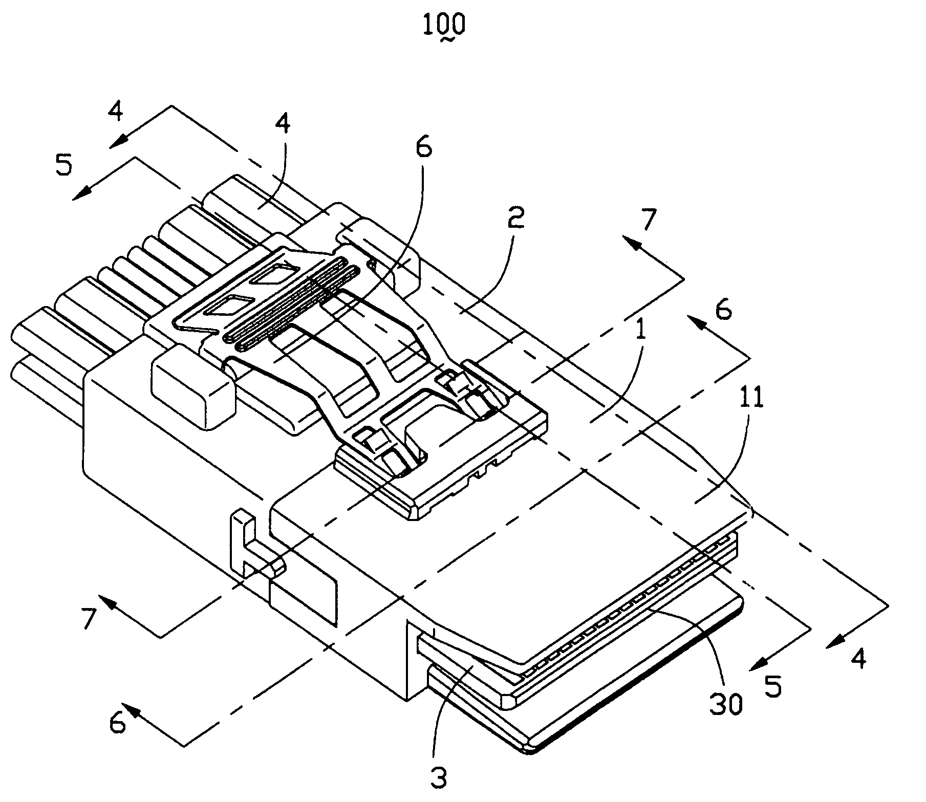
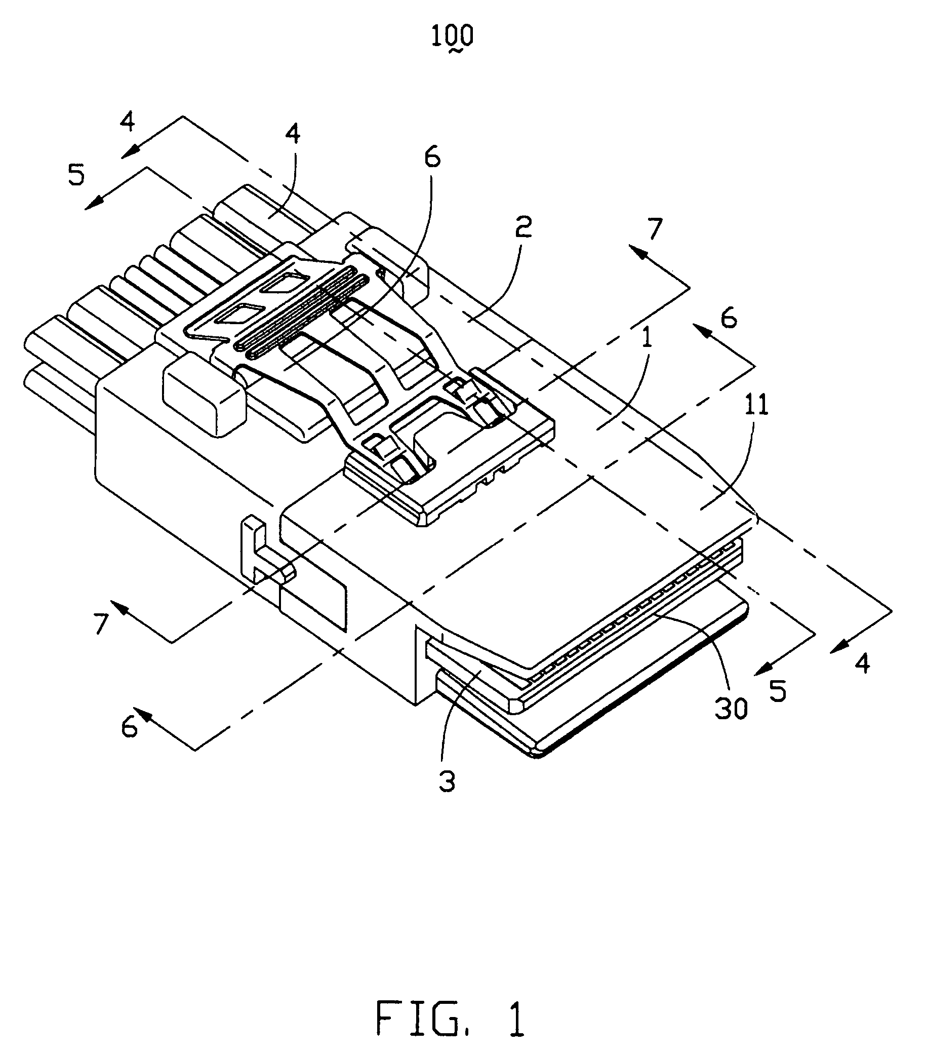
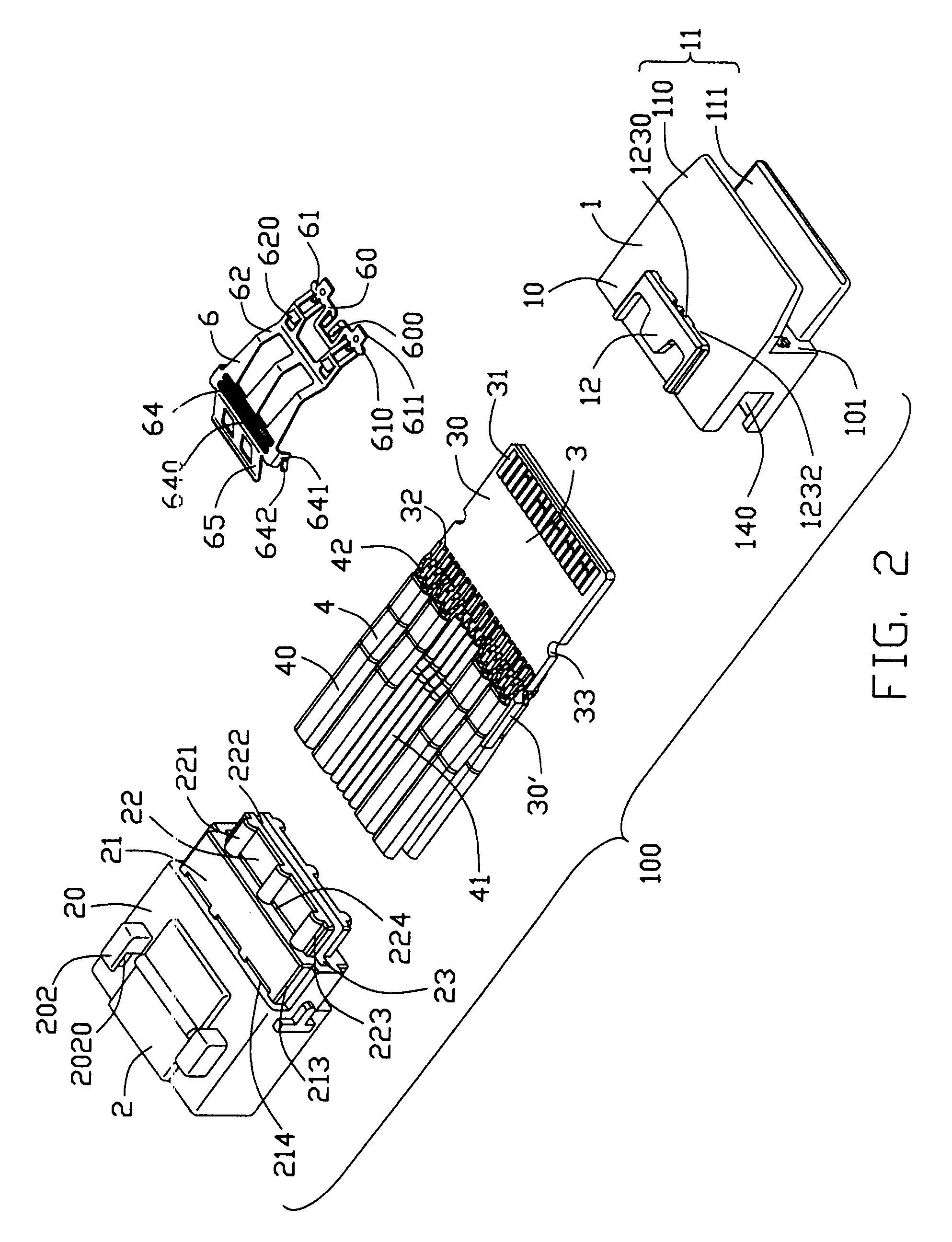
[0022]Referring to FIG. 1, a cable connector assembly 100 in accordance with the present invention comprises a housing (not labeled) comprising a mating direction, a first housing piece 1 with a mating interface 11 formed thereon and a second housing piece 2 attached to the first housing piece 1 along the mating direction, a printed circuit board 3 received in the housing, and defining a mating portion 30 accessible from the mating interface 11 of the first housing piece 1, a cable 4 attached to the printed circuit board 3, and a latch 6 attached with the housing for locking the cable connector assembly 100 with a complementary connector (not shown).

[0023]Referring to FIGS. 1–3 in conjunction with FIG. 5, the first housing piece 1 is made of insulative material with enough rigidity or other material, such as metal. The first housing piece 1 comprises a rectangular body portion 10 defining a central receiving slot 108 therethrough, and the mating interface 11 comprising first and sec...


PUM


Abstract

A cable connector assembly (100) includes a housing defining a mating direction, a first housing piece (1) with a mating interface (11) formed thereon and a second housing piece (2) attached to the first housing piece (1) along the mating direction, a printed circuit board (3) received in the housing, and defining a mating portion (30) accessible from the mating interface (11) of the first housing piece (1), a cable (4) attached to the printed circuit board (3), and a latch (6) attached with the housing for locking the cable connector assembly (100) with a complementary connector.

Description

CROSS-REFERENCE TO RELATED APPLICATION[0001]This application is related to U.S. patent application Ser. No. 11 / 268,951 filed on Nov. 7, 2005, invented by Jerry Wu, entitled “CABLE CONNECTOR ASSEMBLY WITH INTEGRAL PRINTED CIRCUIT BOARD”, which is assigned to the same assignee as this application.BACKGROUND OF THE INVENTION[0002]1. Field of the Invention[0003]The present invention relates to a cable connector assembly and method of manufacturing the same, and more particularly to a cable connector assembly used for high-speed signal transmission.[0004]2. Description of Related Art[0005]A committee called SFF is an ad hoc group formed to address storage industry needs in a prompt manner. When formed in 1990, the original goals were limited to define de facto mechanical envelopes within disk drives can be developed to fit compact computer and other small products. Specification SFF-8087 defines physical interface and general performance requirements of the mating interface for a Compact...

Claims


Application Information

Patent Timeline
IPC IPC(8): H01R13/627
CPCH01R13/405H01R43/24H01R13/504H01R9/035H01R12/62H01R13/6275H01R13/6658H01R13/65915
Inventor WU, JERRY
Owner HON HAI PRECISION IND CO LTD
Learn More