
Meander line antenna coupler and shielded meander line

a shielded meander line and antenna coupler technology, applied in coupling devices, waveguide type devices, radiating element structural forms, etc., can solve the problems of reducing the radiated power of requiring oversized and expensive switches, and requiring 20 to 30 db of switching speed, so as to reduce the resonant frequency of narrow band antennas, reduce the low frequency cutoff limit, and reduce the delay per unit length

Inactive Publication Date: 2007-03-13
BAE SYST INFORMATION & ELECTRONICS SYST INTERGRATION INC
View PDF3 Cites 22 Cited by
  • Summary
  • Abstract
  • Description
  • Claims
  • Application Information

AI Technical Summary

Benefits of technology

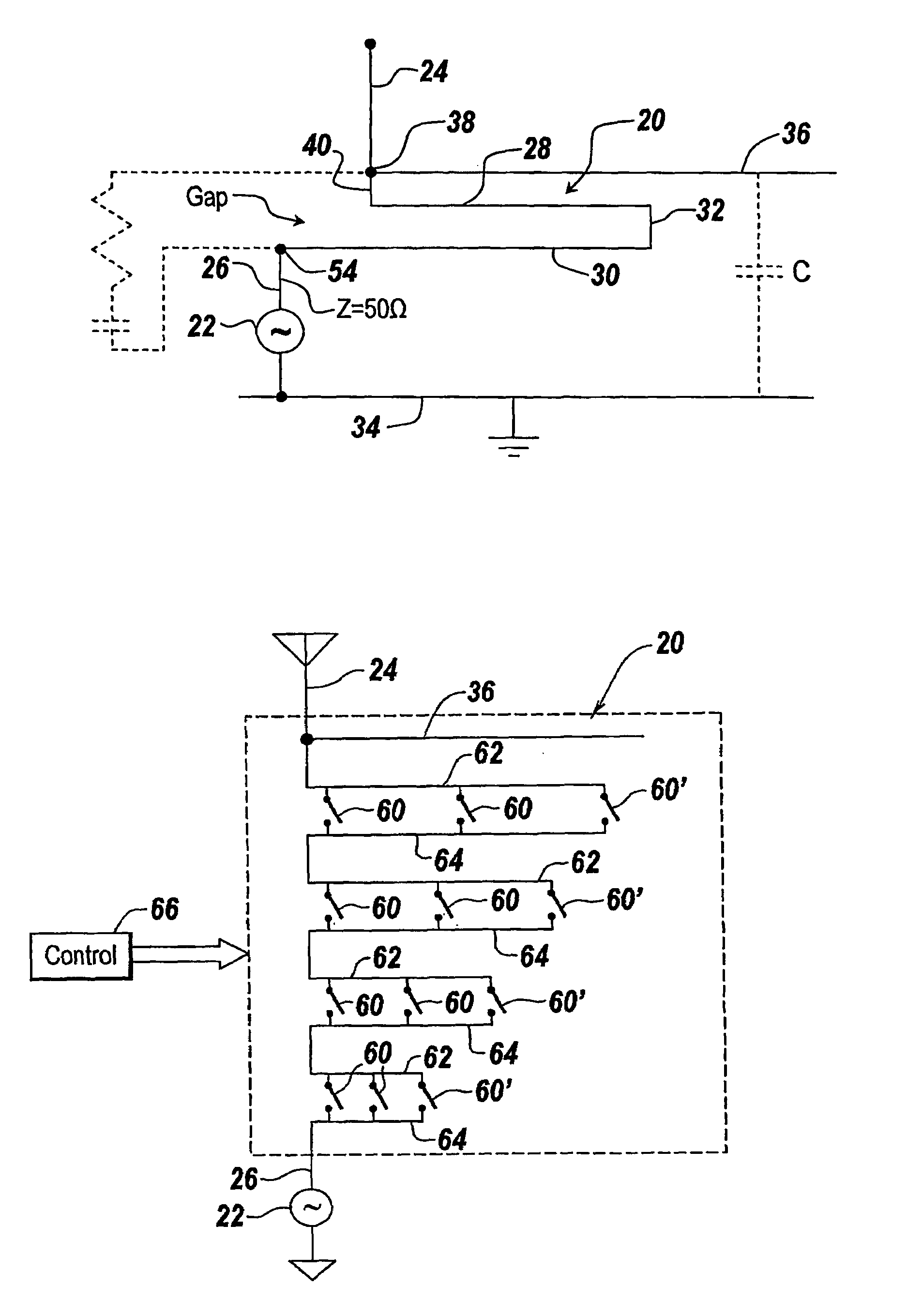
[0013]Typically, the folded sections of the meander line are made out of copper strips which may be one inch wide by one-tenth inch thick. The use of so much metal results in much less ohmic loss as compared with, for instance, Number 12 wire typically utilized in inductors for lumped element couplers.
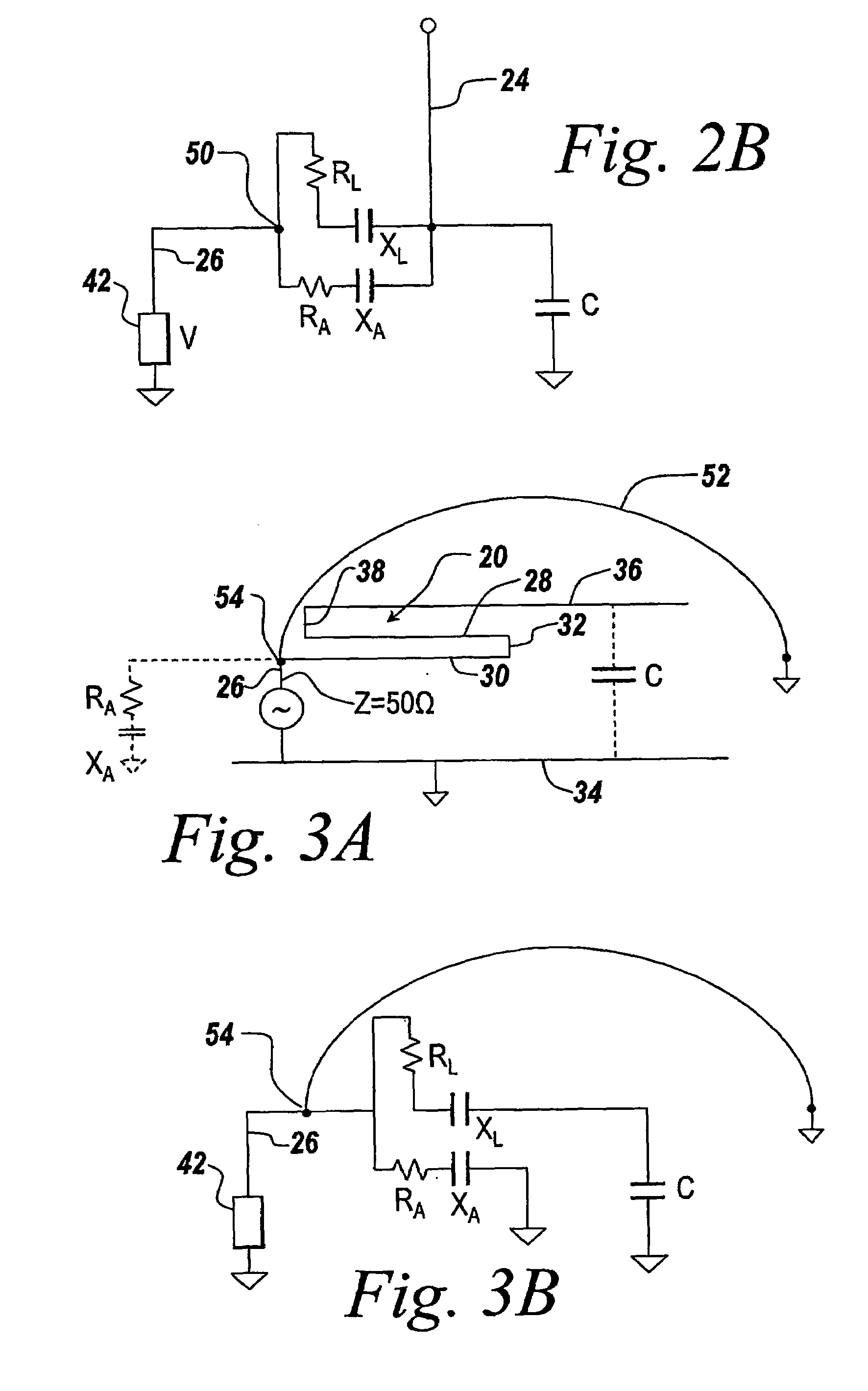
[0049]The shielded meander line may be utilized as a coupling device to truncated antennas such as a whip antenna or grounded loop antenna for the purposes of loading the antenna so as to provide lower frequency performance. Since the propagation constant of the meander line structure depends upon the number of high impedance / low impedance transitions per unit length, the utilization of the top shield results in more phase shifts per unit length and thus more delay per unit length, with the symmetric double sided version having double the number of transitions per unit length. When configured to provide a miniature antenna for use in wireless handsets, the utilization of the top shield both lowers the cutoff frequency and eliminates down firing typical of wireless phone antennas due to the ground plane effect. Moreover, the top shield provides a uniform low VSWR over wide bandwidths and by virtue of lowering the operating frequency solves a skip-induced blackout problem due to the lower frequencies that can now be used. Further, for frequency switched meander lines, voltage stress is reduced by using the top shield. Finally, reducing the volume requirement by over 30% permits mobile use where real estate is at a premium.

Problems solved by technology

Problem with the utilization of such lumped elements center around I2R ohmic heating losses which result either from the relative thinness of the wire utilized in the inductors or internal resistance of the solid state switches.
Moreover, since the solid state switching utilized in these couplers was placed at high-current nodes, oversized and expensive switches were required.
Thus, while mechanical switching was suitable some 40 years ago for antenna couplers, with the advent of frequency-hopping, it is too slow.
Regardless of whether solid state switches were used, the prior lumped element couplers resulted in I2R losses that in turn resulted in a 20 to 30 dB reduction in radiated power.
The ohmic losses are primarily due to the circulating currents in the elements that can rise to huge values to cause the high I2R ohmic losses.
However, as one makes the inductors large, the Qs get too high, which results in extremely high voltages and even greater ohmic losses.
Additionally, with the very high voltages involved with the large components, the diodes that are utilized in the solid state switching are heavily stressed.
Thus, solid state switches for these larger units would have to be extremely massive and expensive.
This means that a considerable amount of the power which should be coupled to the antenna is lost as heat in the antenna coupler.

Method used


Image

  • Meander line antenna coupler and shielded meander line
  • Meander line antenna coupler and shielded meander line
  • Meander line antenna coupler and shielded meander line

Examples


Embodiment Construction

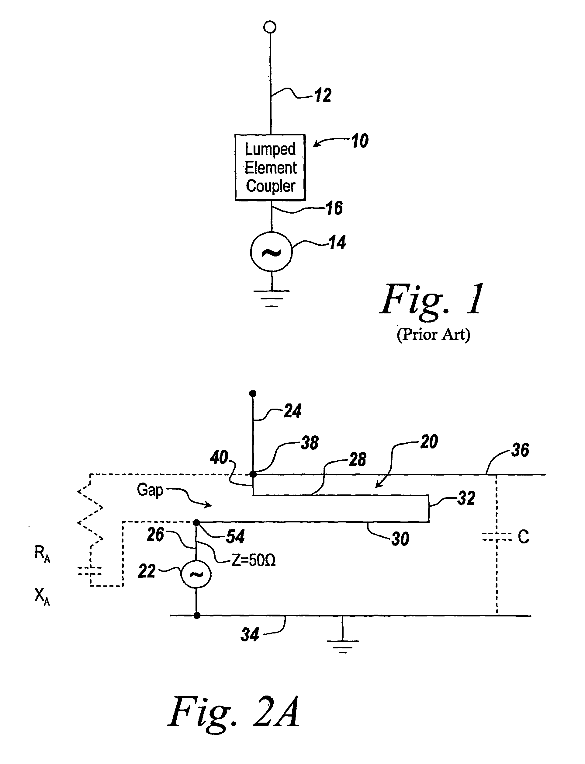
[0077]Referring now to FIG. 1, a conventional lumped element coupler 10 is coupled between a monopole or whip antenna 12 and a signal source 14 coupled between the coupler and ground. As mentioned hereinbefore, whether the lumped element coupler involves pi networks or T networks, each of these networks involves discrete elements in the form of a coiled inductor and a capacitor. Typically, the lumped element couplers act by changing the inductance or capacitance to match the impedance of the antenna to a particular transmission line, here shown at 16. In the case of inductors, the inductors are tapped at various points either mechanically or through switching circuits, whereas the capacitors may be made variable either. by a variable plate or by switching in and out a number of capacitors to provide for the appropriate coupling of the antenna to the transmission line.

[0078]Rather than utilizing a lumped element coupler and referring now to FIG. 2A, what is shown is the use of a mean...


PUM


Abstract

A switched meander line structure is substituted for a lumped element antenna tuner for an order of magnitude increase in gain due to the use of the switched meander line architecture. The use of the meander line with relatively wide and thick folded legs markedly decreases I2R losses over wire inductors whose wire diameters at one-tenth of an inch contribute significantly to I2R losses. Additionally, placing solid state switches to short out various sections of a multi-leg meander line at high impedance nodes reduces I2R losses across the switching elements in the tuner.

Description

[0001]This application is a 371 of PCT / US03 / 34996 filed on Nov. 3, 2003, which is a continuation of U.S. application Ser. No. 10 / 378,336 filed on Mar. 03, 2003 now U.S. Pat. No. 6,894,656 which claims priority of U.S. Provisional Application Ser. No. 60 / 435,099, filed Dec. 20, 2002.FIELD OF THE INVENTION[0002]This invention relates to antenna couplers and more particularly both to the utilization of a meander line architecture for providing the coupler and to a shielded meander line.BACKGROUND OF THE INVENTION[0003]Lumped element antenna couplers have been used in the past to efficiently couple energy into antennas whose impedance is not matched with that of the transmission line. Typically, transmission lines are 50-ohm devices and when using, for instance, whip or monopole antennas, these antennas typically have impedances at the base of the antenna at about 0.05 ohm in the high frequency or HF band. When the transmission line is matched to the impedance at the base of the antenna...

Claims


Application Information

Patent Timeline
Patent Type & Authority Patents(United States)
IPC IPC(8): H01Q1/52H01P5/02H01Q1/36H01Q11/12
CPCH01Q1/362H01P5/02
Inventor APOSTOLOS, JOHN T.MCKIVERGAN, PATRICK D.
Owner BAE SYST INFORMATION & ELECTRONICS SYST INTERGRATION INC
Learn More