Cleaning pad

Inactive Publication Date: 2007-03-20
BUTLER HOME PRODUCTS LLC
View PDF54 Cites 72 Cited by
  • Summary
  • Abstract
  • Description
  • Claims
  • Application Information

AI Technical Summary

Benefits of technology

[0018]It is still another object of the present invention to provide a cleaning pad as described

Problems solved by technology

Although well-known and widely used in the art, dry dusters of the type described above suffer from a notable drawback.
Specifically, dry dusters are designed to electrostatically capture household debris present on a floor but are not designed to wash or scrub a floor.
As a result, dry dusters have been found to be inadequate instruments for thoroughly cleaning a hard floor

Method used


Image

  • Cleaning pad
  • Cleaning pad
  • Cleaning pad

Examples


Embodiment Construction

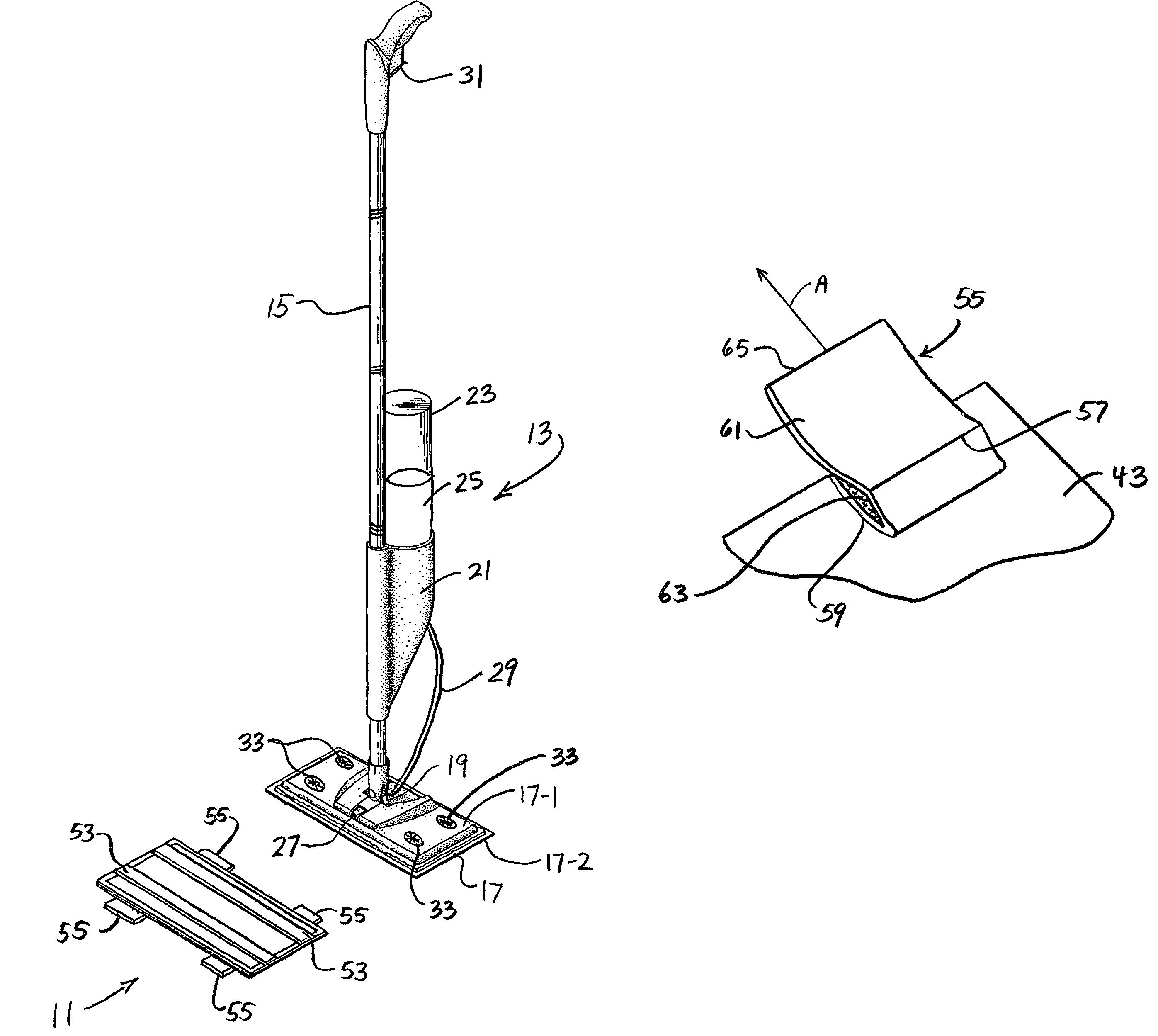
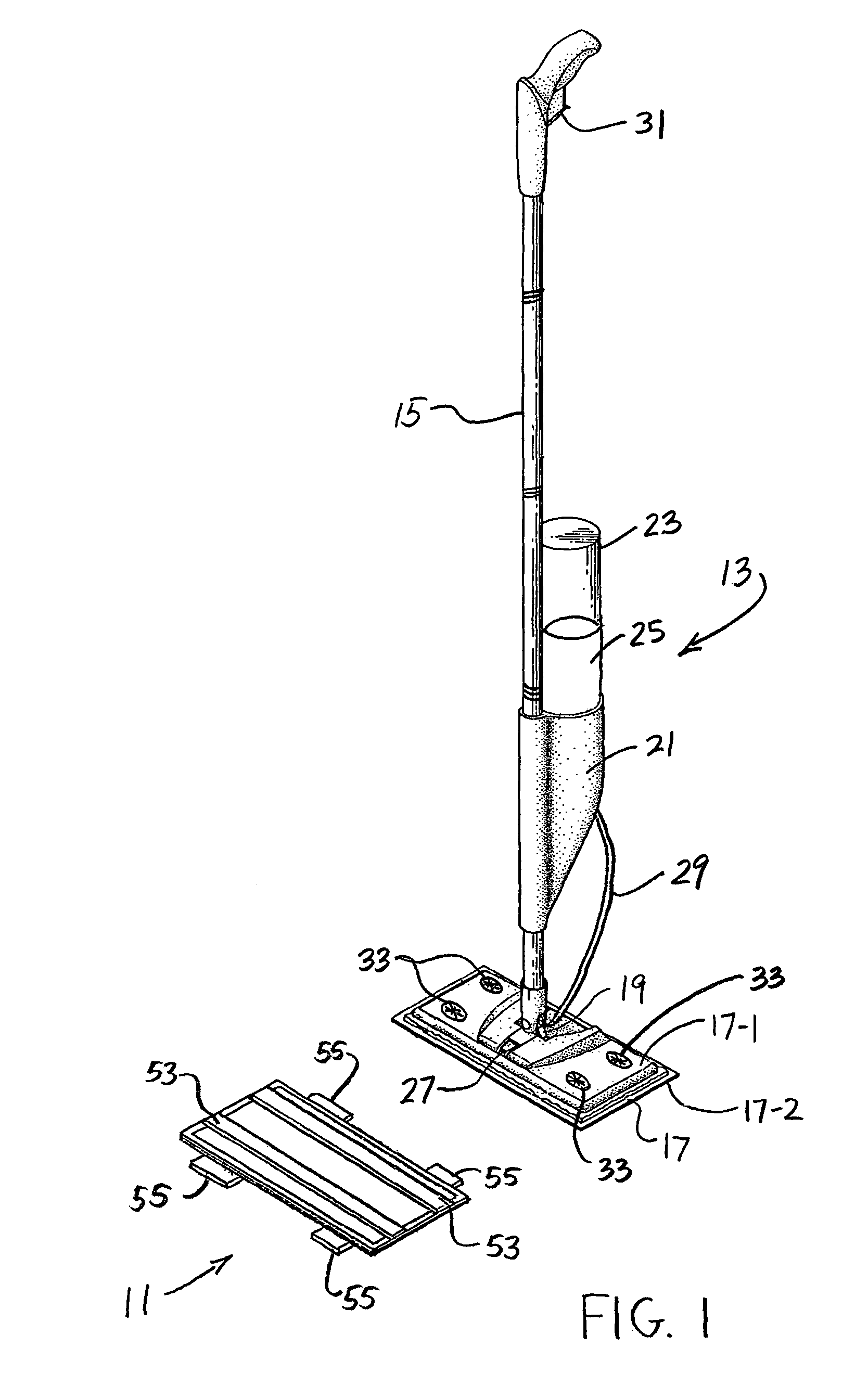
[0027]Referring now to FIG. 1, there is shown a cleaning pad constructed according to the teachings of the present invention, said cleaning pad being identified generally by reference numeral 11. Cleaning pad 11 is shown in conjunction with a cleaning implement 13. As will be described further in detail below, cleaning pad 11 is adapted to be releasably retained onto cleaning implement 13.

[0028]Cleaning implement 13 represents any conventional floor cleaning implement which utilizes removable cleaning pads. Cleaning implement 13 is represented herein as being in the form of a conventional quick clean mop which utilizes removable cleaning pads, cleaning implement 13 comprising an elongated, multi-segment, cylindrical handle 15 pivotally coupled to a flat cleaning head 17 through a universal joint 19.

[0029]Cleaning implement 13 additionally comprises a retainer 21 for releasably holding a container 23 of cleaning solution 25. A nozzle 27 is shown mounted on cleaning head 17 and is con...


PUM

PropertyMeasurementUnit
Distanceaaaaaaaaaa

Abstract

A cleaning pad is adapted to be releasably retained on a cleaning implement which includes on its cleaning head either multiple strips of pile-type fastener material or a plurality of attachment structures. The cleaning pad includes a top layer constructed of polyethylene and a bottom layer constructed of rayon. The top and bottom layers are affixed together along their peripheries by a bond line so as to define an enclosed pocket therebetween which is sized and shaped to receive a middle layer constructed of wood pulp paper. Multiple strips of hook-type fastener material are secured on the top layer and are adapted to releasably engage complimentary strips of pile-type fastener material on the cleaning implement. One or more mounting tabs are secured on the bottom layer and are adapted to releasably engage complimentary attachment structures on the cleaning implement. Each mounting tab can be disposed between a retracted, or folded, position and an extended, or unfolded, position.

Description

BACKGROUND OF THE INVENTION[0001]The present invention relates generally to cleaning implements and, more particularly, to floor cleaning implements.[0002]Floor cleaning implements are well-known and widely used in commerce to clean hard flooring surfaces, such as ceramic tile, hardwood, vinyl, laminate, linoleum and marble floors.[0003]One type of floor cleaning implement that is well-known and widely used in the art is a dry duster, also commonly referred to in the art as a sweeper. Examples of some well-known dry dusters are shown in U.S. Pat. Nos. 6,513,184, 6,484,346, and 6,305,046 and include the.[0004]A dry duster of the type noted above is designed to capture onto a disposable, electrostatically-charged cloth light household debris, such as dust, dirt and hair, from a hard flooring surface. Typically, a dry duster comprises an elongated cylindrical handle which is pivotally coupled to a flat sweeper head through a universal joint. The flat sweeper head is adapted to releasab...

Claims


Application Information

Patent Timeline
IPC IPC(8): A47L13/10A47L13/20
CPCA47L13/20
Inventor MICHELSON, ROBERTDUNN, THOMAS
Owner BUTLER HOME PRODUCTS LLC
Why Eureka
Try Eureka