Thermopneumatic microvalve

a micro-valve and thermopneumatic technology, applied in the field of microfluidic devices and systems, can solve the problems of large operating voltage, complex structure, and large actuation power, and achieve the effect of reducing the number of devices

Active Publication Date: 2007-03-20
RGT UNIV OF MICHIGAN OFFICE OF TECH TRANSFER THE
View PDF5 Cites 43 Cited by
  • Summary
  • Abstract
  • Description
  • Claims
  • Application Information

AI Technical Summary

Benefits of technology

[0011]According to one embodiment, the microvalve device may also include an insulating layer disposed on portions of the semiconductor-based valve housing. The capacitor may include a first electrode and a second electrode, where the first electrode is disposed on the valve face and a voltage is applied across the first and second electrodes to electrostatically hold the valve face in the second position. The insulating layer may then be further disposed between the first and second electrodes to prevent contact of the first and second electrodes when the valve face is moved from the first position to the second position.

Problems solved by technology

Electromagnetic microactuators have been demonstrated, although magnetic forces scale unfavorably for devices with small volume.
Piezoelectric actuators have shown substantial actuation force and fast response times, but have also required large operating voltages and a complex, stacked hybrid construction in order to achieve substantial actuation displacement.
Unfortunately, shape memory alloy (SMA) and bimetallic thermal actuators (i.e., bimorph structures) have tended to require significant power for actuation, typically hundreds to thousands of milliwatts.
Thermopneumatic microvalves have also been reported, but the typical overall power consumption of such valves has also been undesirably high.
However, such microvalves have been susceptible to particulate contamination and weak actuation force over large distances.
Electrostatically actuated microvalves have been unsuitable for applications requiring long valve throw (i.e., large valve travel distances) and accordingly been designed with low-flow rate applications in mind.
However, such approaches to bistable valves are burdened by complexity in both design and fabrication process, and are also unsuitable for high pressure applications.

Method used


Image

  • Thermopneumatic microvalve
  • Thermopneumatic microvalve
  • Thermopneumatic microvalve

Examples


Embodiment Construction

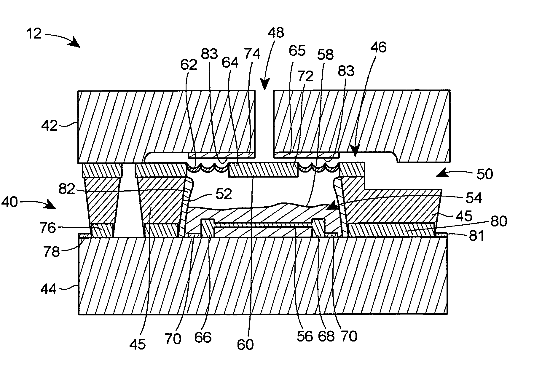
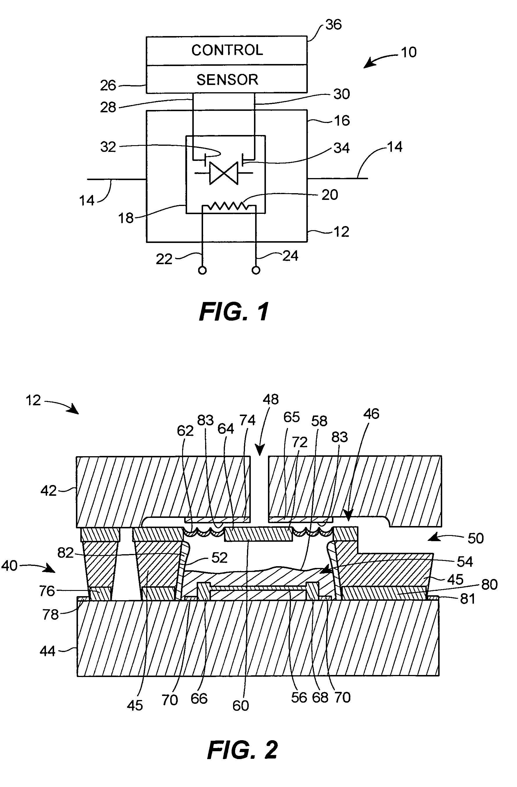
[0021]Described herein is a microvalve design having an actuation mechanism complemented by a latch or hold such that the microvalve consumes power only during valve displacement or transitions from one stable state to another stable state. More particularly, the advantages of thermal-based actuation are combined with the benefits of electrostatic latching to provide bi-stable microvalve functionality with ultra-low power consumption. Further efficiencies are gained through the use of a sensor to determine accurately when power should no longer be applied to the thermal-based actuation mechanism such that power is only substantially consumed during the transitions. Power consumption during the transitions may also minimized with an insulated cavity that prevents unnecessary heating of the device outside of the actuation mechanism as described in greater detail hereinbelow.

[0022]Thermal-based actuation such as thermopneumatic drive mechanisms provide high force, small size, large val...


PUM


Abstract

A microvalve device includes a semiconductor-based valve housing that defines a flow passage, and a valve face disposed within the valve housing and in fluid communication with the flow passage. The microvalve device further includes a thermal expansion actuator that drives movement of the valve face from a first position to a second position relative to the flow passage, and a capacitor that holds the valve face in the second position. The microvalve may also include an insulating layer disposed on portions of the semiconductor-based valve housing, and a capacitance sensor for monitoring a capacitance level to determine when the valve face reaches the second position. Once the sensor indicates that the second position has been reached, power is no longer applied to the thermal expansion actuator such that power is only substantially consumed during the transition from the first position to the second position. The thermal expansion actuator may include a heating element and a thermal expansion substance for thermopneumatic displacement of the valve face.

Description

RELATED APPLICATION[0001]This application claims the benefit of U.S. provisional application entitled “A Latching Thermo-pneumatic Microvalve For Ultra-Low Power Applications,” filed May 8, 2003, and having Ser. No. 60 / 468,868.STATEMENT REGARDING FEDERALLY SPONSORED RESEARCH OR DEVELOPMENT[0002]This invention was made with government support under Contract No.: EEC-9986866 awarded by the National Science Foundation. The government has certain rights in the invention.GENERAL FIELD[0003]The disclosure relates generally to microfluidic devices and systems and, more specifically, to microvalves having ultra-low power consumption.BACKGROUND[0004]Valves and their miniature counterparts, microvalves, control the flow of fluids (e.g., gas or liquids) in fluidic systems. Microvalves have generally improved fluid flow control in applications where the significant power demands of a macro-scale valve would be unsuitable. Microvalves also generally avoid large dead volumes—the undesirable empty...

Claims


Application Information

Patent Timeline
Patent Type & Authority Patents(United States)
IPC IPC(8): F16K31/00F15C5/00F16K99/00
CPCF15C5/00F16K99/0001F16K99/0009F16K99/0059F16K99/0044F16K2099/008F16K2099/0074
Inventor WISE, KENSALL D.POTKAY, JOSEPH A.
Owner RGT UNIV OF MICHIGAN OFFICE OF TECH TRANSFER THE
Why Eureka
Try Eureka